Beginner's Arduino Programming Thread

This is a thread where I’m going to work on / present some basic programming for beginners. I will be working with an Arduino based kit that can be found HERE on Amazon for 29.99

If you’re in the U.K, it can be found HERE. Thanks again to @Atilla for the link.

If you’re in neither place, I suggest you search your local Amazon for the following:

Because I fear that alot of discussion and cross chatter will completely derail the lessons, I’m going to have this thread locked. However I have provided THIS THREAD for all questions / comments, etc.

To the Newbs.
This ain’t that hard, and I’m gonna keep it all super basic. Please feel free to ask anything. I know from experience the community will go all in on helping you out. Also, if you can’t swing the cash for the kit, there is a free option for a simulator. I think you’ll get much more from being hands on, but broke is broke, I get it.

To the Accomplished Programmers:
I am not an accomplished programmer, just a dude trying to help others along. Please feel free to chip in, but just remember you’re dealing with people who are just starting out. I’m gonna do the lessons wrong too, I’m sure. Feel free to correct me, I’ll take it in good spirits, just please don’t muddy up the waters for the new people.

And THANKS to ALL for Playing!

8 Likes

The following two videos are our jumping off point. They’re long and boring, sorry. Just gotta cover some basics to get started.

Video #1 Covers the kit we’re using.

Video #2 Covers the programming software, and the optional simulator for if you don’t wish to buy a kit.

4 Likes

There are many programming languages. Some common ones include C, C++, C#, Python and Java. (Bonus points if you remember Fortran!) The Arduino’s Programming is based off of and pretty similar to C. Like any language it has it’s own specific words. Unlike many spoken languages it only has a small number of them. A list can be found HERE.

In practice, most people only use a small portion of that list. Think of it this way, there are only 26 letters in the english language, yet it encompasses everything from knock-knock jokes to “The Grapes of Wrath”. It’s all in how you order them.

Speaking of order. This is a language that is designed to be written by a person, but READ BY A MACHINE! While humans can undurstend purly writtin wurds, a computer cannot. Each word must be typed and puctuated exactly according to the way it is intended to be used. If you don’t, the machine will simply state that if found an error and go no farther until you correct it. It’s best if you pay attention while writing so that you don’t have to go back and fix a bunch of mistakes.

Let’s look at the words we’ll be using in this first example.

Structure:

void setup() { }
This contains all the setup data for our program it runs once at the beginning and everything we do there goes INSIDE the brackets { here }

void loop() { }
This contains the main body of the program. It will work from the top to the bottom and then go back and do it all over and over and over. Once again everything must go inside the brackets.

First part of program (in setup).

pinMode(pin, mode)
This allows us to set a specific pin (the black holes on the edge of the arduino where you put wires in) as either an input or an output. This is a digital command, so it’s either on or off. The arduino has both digital and analog pins. You can use the analog pins as digital pins if you want, but not the other way around. To use it, set pin to a number, and mode to either input or output. Example pinMode(4, OUTPUT) Note the EXACT capitalization, punctuation etc. This command will only be used in the setup portion of the program. It’s just to let the arduino know to expect to use that pin for this thing.

Main Body of programming (in void loop).

delay( )
This command pauses the program for an amount of time in microseconds. So if you want a one second pause, delay(1000) and you got it. In practical terms a program goes much too fast for you to see it’s real world effects. This is usually used to slow it down to allow you to see / react to it.

HIGH
This simple command specifies something turned on. In the arduino’s
case, that means +5v on wire.

LOW
Same as HIGH, but turned off, 0v.

digitalWrite( )
This command tells the arduino to put a specific pin in either HIGH, or LOW condition. For example. digitalWrite(4, HIGH) will set pin4 to a HIGH condition. Basically you’re just turning the wire on or off. This is actually a very powerful command for turning programming into real world results. You can use this to turn on a relay which can then unlock your car door or open your garage door.

Other important things.

  1. Each programming line MUST END with ; Please note, that’s not a :
    It makes a huge difference.
  2. It’s common practice, and a really good idea to write notes to yourself INSIDE the code. When you write // Everything to the right of that will be ignored by the machine for the remainder of that line. So you can write a little description of what it’s supposed to be doing there. This is super helpful when going back over your stuff later.

Now that all that’s been said, let’s put it together for a first program. The following program is blatantly ripped off from the Arduino example code.

void setup() {
  pinMode(13, OUTPUT);    // sets the digital pin 13 as output
}

void loop() {
  digitalWrite(13, HIGH); // sets the digital pin 13 on
  delay(1000);            // waits for a second
  digitalWrite(13, LOW);  // sets the digital pin 13 off
  delay(1000);            // waits for a second
}

You can type that in, or just pull it up from the example sketches. The reason we use pin 13 is because the arduino has a built in LED connected to pin 13. You should be able to look at your board and see it flashing according to the pattern set in the program while working.

Next, I will show you how to setup and run that program on the Arduino hardware.

6 Likes

One of the most interesting and useful features of the Arduino is the ease with which you can attach and read a huge variety of sensors. Which brings us to how to read those sensors. While every sensor is different, the vast majority will report back a reading as a partial voltage. If you have a sensor measuring something, say how light / dark it is on a 5v system like the Arduino, then you might expect the following.

Full Dark 0v

25% Light 1.25v

50% Light 2.5v

75% Light 3.75v

100% Light 5v

With every possible voltage in between as the light level creeps up or down. The returned signal then is Analog in nature.

What analog means is that a signal can have an infinite number of states, it can always be just a little more or a little less. The problem here is that the Arduino is a Digital device. It expects a single discrete answer, yes or no, on or off, high or low. It has no maybe, sorta, or middle.

This was allowed for when the Arduino was designed by using some special internal circuitry that is attached to just some of the pins. If you examine the Arduino you will note that there are labels on the pins that divide them into groups.

In particular the group labeled as “Analog In” can accept an analog reading when used with the following command.

analogRead( )

This command will tell the arduino to check the voltage on one of the analog in pins, and convert it to a digital number. For example, the command analogRead(A3) will tell the Arduino to check the pin A3, and return a number from 0 to 1023 based on the 0 to 5v scale. Our previous light based sensor example then, would give the following results.

Full Dark = 0

25% Light = 254

50% Light = 511

75% Light = 767

100% Light = 1023

This isn’t an actual Analog input, because that would require an infinite number of possibilities, but by chopping it up into 1024 possible results, we can fake it so good that it no longer matters.

The Arduino can also fake an Analog output, but once again, only on specially designated pins, and only within certain steps.

When writing an analog output the Arduino uses only pins 2 through 13. You will see them marked as a group PWM on the board. This stands for Pulse Width Modulation. The idea is very simple, the Arduino pulses, or turns on and off, the pin so fast that it appears to be a partial voltage. If I wanted a 2.5v output then I would want the relative amount of ON time to OFF time to be 50%. If I wanted a lower voltage, I would need less on time and more off time. There are 256 available levels of output, and they are 0 through 255

The command is

analogWrite( )

For example, if I want to put an output of 50% or 2.5v on pin 6, then I would choose a number in the middle of that scale and write the following. analogWrite(6, 127)

So why would I want this? Two reasons, 1, because some things use this as a signal. An excellent example are RC servos, which use that PWM signal to determine what position to move to. Change the signal, and the servo moves. Reason 2, many simple devices need a specific voltage or a variable input. This can be used to speed control a motor, or to dim an LED.

In order to write a useful bit of code to demonstrate these we will need one additional concept.

Basically, we need a place to store the numbers from the analogRead and a place to put numbers for the analogWrite. There are different types of data storage available, but we are going to use the simplest. It is called int, and it stands for integer. It can basically be used like X in algebra, it stands for whatever is stored in it, and can be used in place of a number anywhere in the code. It can be used to store ONLY whole numbers from -2,147,483,648 to 2,147,483,647. That’s a big enough range that you shouldn’t exceed the limits. If you do, it just cuts off the extra and stores whats left causing bad data or an error, you’ve been warned. It also cuts off partial numbers. If you try to store 3.6, then it stores 3 and drops the .6 entirely.

To use it, you must first set it up before the setup section by giving it a name. In this example we’ll set up two int called Innie and Outtie. The commands then would be :

int Innie = 0

int Outtie = 0

The 0 in this example tells it to go ahead and assign them a value of 0. This is extremely good practice in programming. If you leave off the “= 0” then it still works, but the value is going to be whatever random thing got left in storage from previously. This can wreak havoc on your program’s execution.

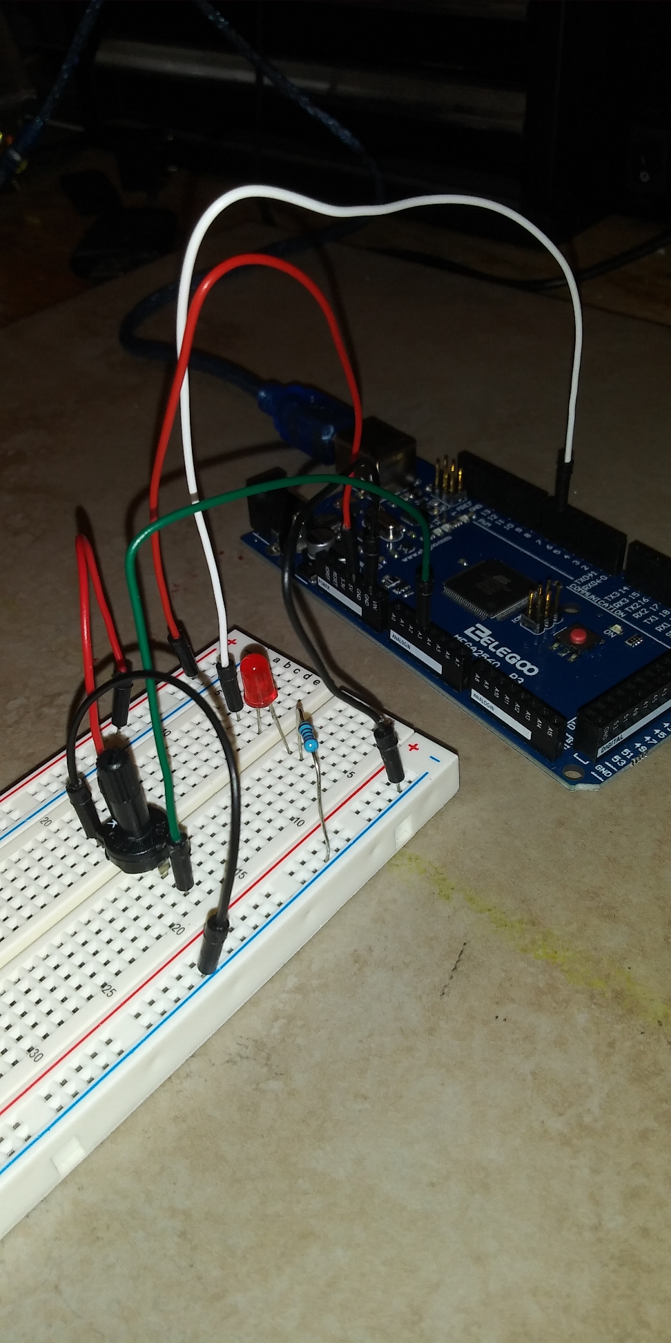
We’re gonna need some wiring to run this on. For an output, we’ll have an LED setup in pin 6, and for an input we’ll use the potentiometer in the kit (see video) on pin A3.

Let’s put it all together then.

int Innie = 0; //creates Innie and assigns it 0
int Outtie =0; //creates Outtie and assigns it 0

voidsetup( ) {

}

void loop( ) {
Innie = analogRead (A3); //this reads pin A3 and assigns a 0-1023 to the int Innie
Outtie = Innie/2; //this is simple math, it cuts the number in Innie in half to scale it down to the range of 0-255 and puts it in Outtie
analogWrite(6, Outtie); // this sets pin 6 to a PWM whose strength is between 0-255 based on the number in Outtie
}

EDIT; As a very observant @Locutus pointed out I should have divided by 4, not 2. These are the little mistakes that trip up all programmers. Details details details.

Arduino / Programming Chatter Thread - #9 by Locutus

2 Likes