If anyone can help I’ve got a completely non Rfid project. I’m trying to fix a treadmill and thought maybe one of the awesome people on this forum could help ![]() . Trying to fix a treadmill for my wife. When you turn it on it revs up and goes about 16mph. If anyone is interested in a good puzzle let me know and I’ll post more info. The control board is popular for diy lathes and sanders so I’m hoping someone has worked with it before it’s a MC-60.
. Trying to fix a treadmill for my wife. When you turn it on it revs up and goes about 16mph. If anyone is interested in a good puzzle let me know and I’ll post more info. The control board is popular for diy lathes and sanders so I’m hoping someone has worked with it before it’s a MC-60.
TIA
Dan
Depends on if you have measuring equipment. Do you have a multimeter? Also, have you considered buying a replacement MC-60 for $60 on eBay?
I have a multimeter but that’s it. I have thought about buying a new one but I’m also using this as a learning experience. The treadmill was free so I’m trying not to spend a lot fixing it. I’ve found a few schematics of the board but am stuck trying to figure out the problem.
I’m willing to try and help. It will be much easier with a multimeter.
I’m assuming 16mph is pretty fast for the treadmill. That would lead me to believe that it’s either not receiving instructions from the control panel, or that there’s a short or damage components causing it to perform the incorrect action.
I think the first thing to check is whether the box is getting unreasonably hot when you run it. If you’re getting runaway heat buildup, there’s very little chance you can fix it, because many of the components will likely have been damaged by overcurrent in a cascade of failures.
If there box is staying at a manageable heat level while you run it, you can probably do something. This guy seems to know what he’s doing

I’d check the resistance values on the speed control potentiometer with your meter, make sure it’s connected up well. It’s
If it still doesn’t work, carefully check the DC voltage on the motor contacts. It’s probably 12V.
2 Likes
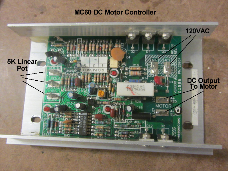
My first instinct when I read your post was to check if the speed sensor(if it exists) has gone bad. Given the diagram @Satur9 posted I would check the values on the pot first and make sure it is within acceptable bounds. So set your multimeter to ohms and check the outer two pins first. They should read 5k ohms. Then make sure the pot is set to the middle and check from the outer pins to the inner pin. Tou should see 2.5k (assuming it is a linear pot). If the reading from the inner pin is bouncing around a lot when you move it then you might try getting a can of Deoxit and spray it into the pot. It could just be dirty and giving you a false reading.
2 Likes
Ok so it looks my pot may be 2k?
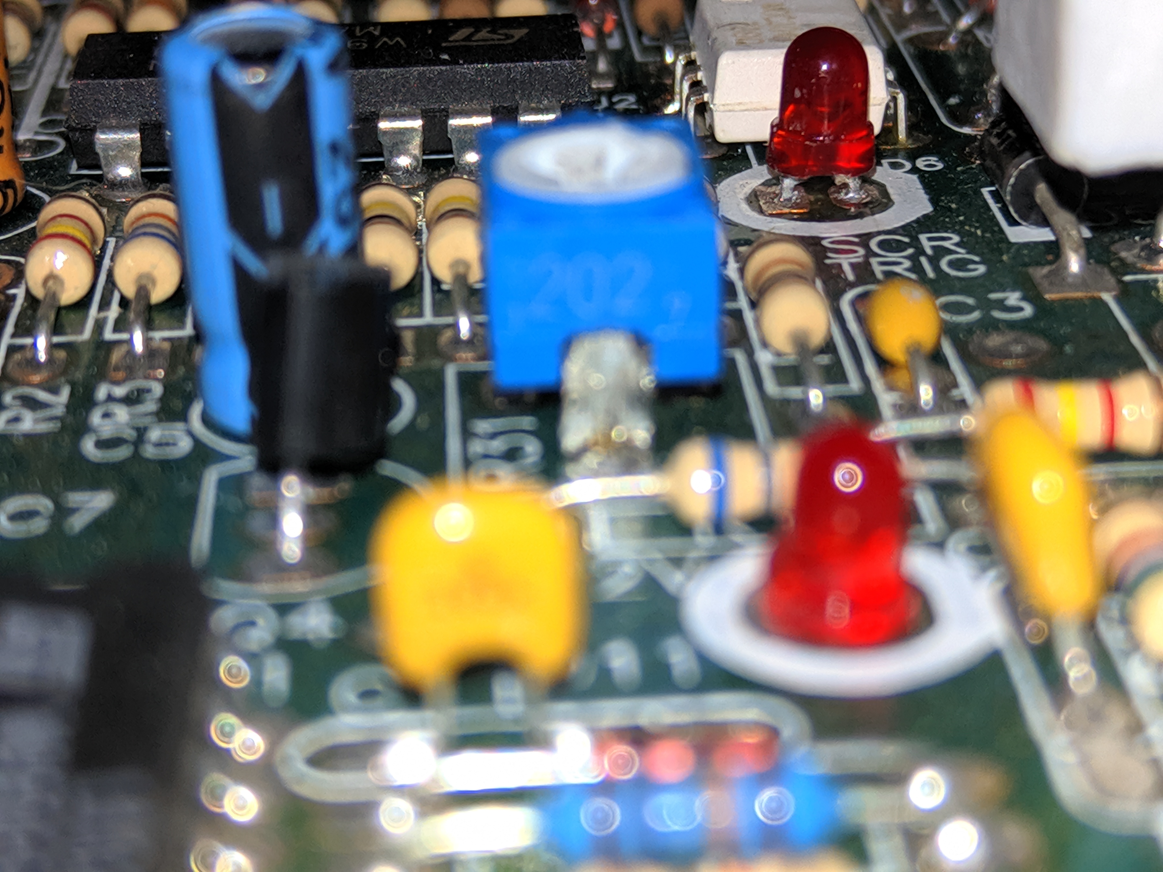
When touching the two pins closest to each other with the multimeter set to 20k ohms I get a reading of 1.51.

Then between fixed end 2(left) and the variable end is 0.0
Between fixed end 1(right) and variable end is 1.56
That first picture only shows the trim pot. Could you post a picture of the entire control board and the external potentiometer?

Excellent! at the top of the board you see those Red, White, and Black wires? While it is turned off ( probably obvious but safety first ![]() ) unplug the black and red wires and measure the resistance between the wires (not the board). Then measure from Black to White and Red to White. The pot those wires are connected to is probably on the controls at the helm of the treadmill. Make sure that slider is set to the middle of its travel.
) unplug the black and red wires and measure the resistance between the wires (not the board). Then measure from Black to White and Red to White. The pot those wires are connected to is probably on the controls at the helm of the treadmill. Make sure that slider is set to the middle of its travel.
We want to see the following
- Resistance from RED to BLACK:
- Resistance from RED to WHITE:
- Resistance from BLACK to WHITE:
That should tell us if there is a problem with the potentiometer or the controlboard.
1 Like
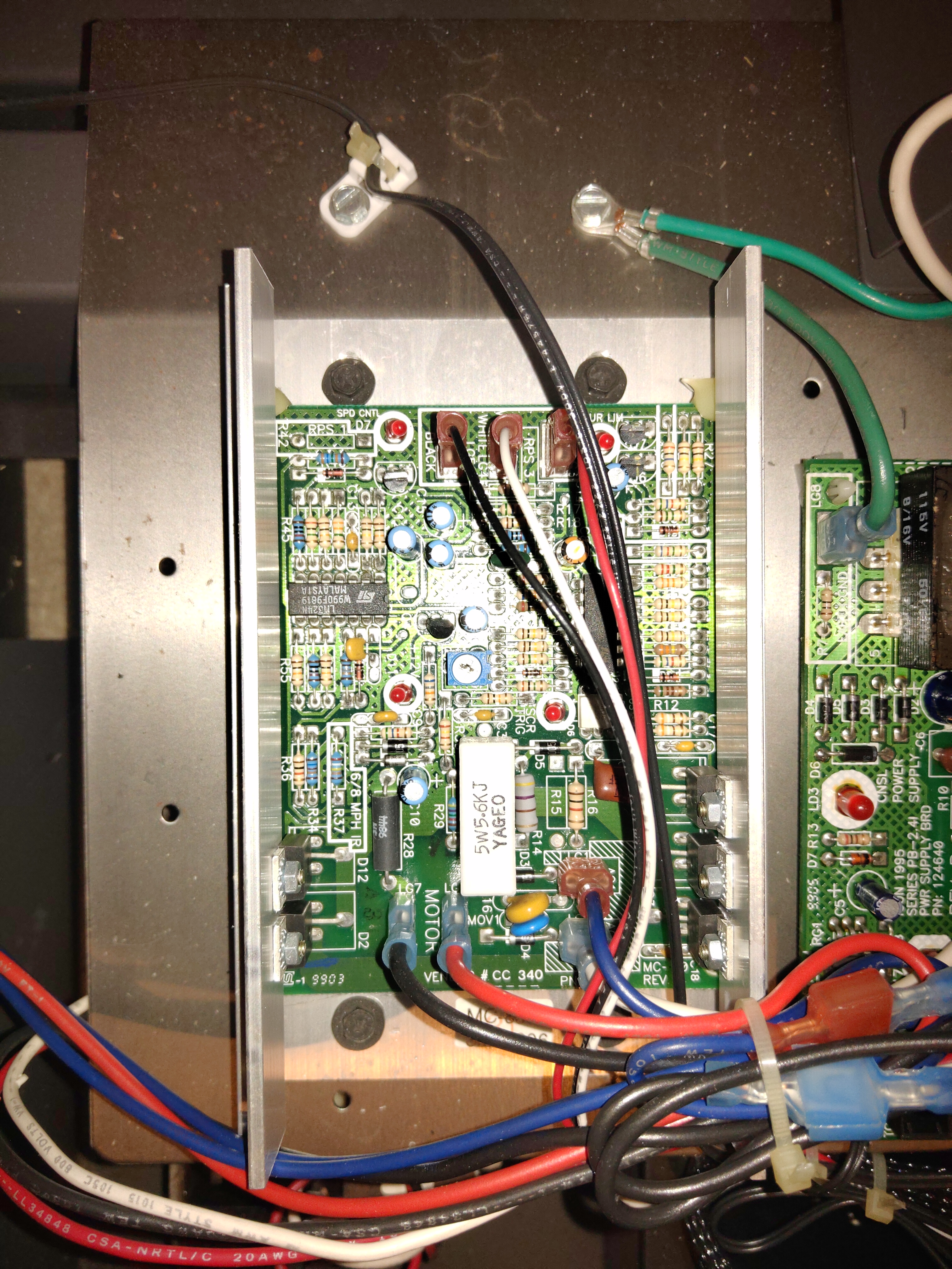
Ok so the black white and red on the control board go to the plug on the lower right of the power board. I unplugged all three wires before testing hope that’s ok. Didn’t get steady readings on red to black or red to white, I’m not sure if my multimeter doesn’t go high enough for red to black/white with the meter set at 2000k the meter would blink anywhere between 400 and 980, with the meter set at 20k the reading between black and white is 5.12.
That is a strange one. Does the treadmill use a digital control panel?
Yes it does. The speed is supposed to be read by a reed switch. And from what I can tell from the diagnostic mode the board is receiving the info. That’s how I know it’s at 16mph. But when it’s not in diagnostic mode the speed shows 0, if I hit the speed up button it doesn’t affect the belt, but the display changes.
Did I stump you? Lol. Still trying to trace the issue but no luck yet.
Oh Sorry. I got distracted and completely forgot about it. Yeah that think has me pretty stumped. I don’t recommend it since there is plenty of high voltage in there but probing the voltage between black and white wires might tell us if the smarts in the treadmill is malfunctioning. The last think I might try is disconnecting the black white and red wires then making a 1/4 or 1/2 resistor voltage divider. ![]() Beyond that I don’t know.
Beyond that I don’t know.
If it helps I found something that had me unplug the those three wires and jump the red and white terminal and if the speed control lit up the board is good so now I’m wondering if it’s the power board not the control board that is the problem. And don’t worry about answering anything I say right away we all have our own stuff.
PWW Motor Controller.pdf (380.7 KB)
Random not-immediately-useful thought:
If all else fails and you have to get the missus a new treadmill, the old one probably has a 90V DC permanent magnet motor in it that’s run by a small serpentine belt. These make great little generator motors if you wanna try a homebrew windmill generator setup. Some assembly required, batteries not included.