Coil Inductance Calculator

I’ve been designing inductor coils to serve as NFC antennas a bunch lately. I tried some online calculators and they were hit-or-miss. I combed through some Application Notes published by the popular NFC chip manufacturer NXP and discovered some reliable information on designing PCB trace inductors for NFC applications. I used this information to create a small java applet that runs in the command line. Here is everything you need to run it zipped up:

Inductance_Calculator.zip (106.1 KB)

In the package you’ll find:

  • [[CLICK_ME_TO_RUN]].bat
    A short batch script to initiate the program in the command line on windows machines
  • IndCalc.jar
    The actual java archive
  • NXP_AN1445[46-48].pdf
    A snippet of the NXP Application Note I used to create the calculator

I experimentally verified the results using a quality LCR meter on two different PCBs I designed (admittedly not a huge sample size), and compared the results to other calculators I found online. It seems valid. This calculator is intended to be used for PCB trace antennas, but with some careful consideration you could definitely figure out how to get reliable results for wire-wound inductors as well.

If you end up getting some use out of this, let me know how it went.

6 Likes

Do you have a footprint for a 13.56 coil in a spiral with hollow centre ? Id get one from OSH Park on flex PCB for some testing ! I also have been looking for resources and haven’t found much, my background is sort of technical but there are lots of gaps haha :sweat_smile:

Here are some additional calculators that I vetted. They’ll help out with some tangential stuff you might need to do.

LC Tank Circuit Calculator:

Wirewound Coil Inductance Calculator:
http://www.66pacific.com/calculators/coil-inductance-calculator.aspx

Yeah, I can help you out. First off, what PCB CAD software are you using? I primarily use Eagle (Autodesk), but I’m sure I can help you out with KiCAD or EasyEDA or whatever you’re using.

You can use the Java applet I shared to figure out the appropriate coil dimensions, but you need to know what the ideal inductance is for your circuit first. What are you using to generate the 13.56MHz signal?

Just as a reminder / context, she’s wanting to make a power coil for her xLED :slight_smile: My hunch is that it will have to traverse her xLED… I don’t think it will light if the xLED is in the center of the coil (in the hollow bit)… at least this is not how other readers tend to work anyway… worth testing with a different reader first to get an idea of performance before you go about building your own coil.

Yup, I was checking out leeborg’s other post. I’m familiar with her project.

@Leeborg
You might not want to do a flex PCB, because of the limitations Amal described. You would have to lay the spiral antenna over top of your implant to get it to couple well (which would block the light and defeat the point). Here is a simulation of the magnetic field generated by a spiral coil:
free_17764

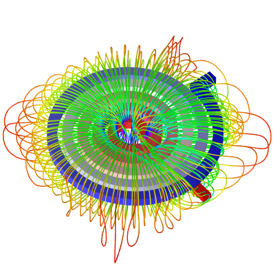
See the green part of the flux lines? That’s area with the greatest flux density in parallel with the coil in the xLED. You could imagine it like each flux line was the trajectory of a ball being tossed up in the air. The ball never reaches escape velocity (where it would become an RF signal) so it inevitably has to fall back down to the “gravity” of the center of the coil. I really doubt the red parts of the field would power your xLED.

What might work better is a wirewound cylindrical coil shaped like this:

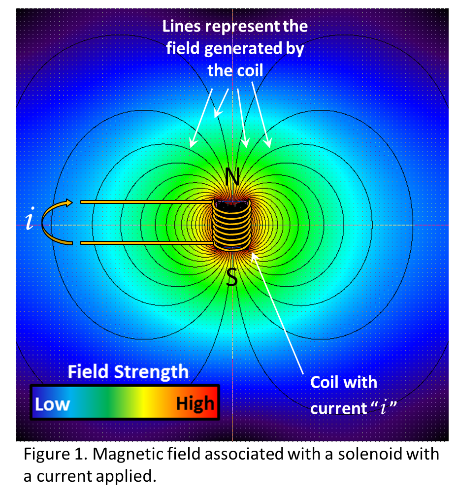
That way you could situate the coil next to or above the xLED and still get pretty good coupling, without covering up the light.

2 Likes

Hmm okay makes sense. I guess I’m curious then Why are inductive charging coils flat ?

Inductive charging coils are flat because two flat coils couple very well, so a lot of power can be transferred over short distances. The field is also distributed over a large surface area, so the user doesn’t have to perfectly position the coils for it to still work pretty well.

The situation we have here is a cylindrical coil (xLED) trying to couple with a flat coil (PCB Trace antenna) which is definitely less than ideal. The fields are completely different shapes. You could probably get it to work, but you’re going to need to figure a bunch of tangential stuff out first. Plus, you don’t need tons of power, just ~20mA. You mine as well make it easier on yourself for the first couple prototypes.

Okay. I hear you and I’m trying to understand. Can you explain why this works and the coil doesn’t work with the xLED? The small ones are cylindrical coils like the xLED
https://www.instagram.com/p/B2NOFe4gUS2/?igshid=w9j3cziiij2x (video as well as image)

They are also all different frequencies. I am confused :frowning:

No worries, you’re confused because it’s confusing. It’s taken more than a minute for me to mostly figure out this stuff, it’s not going to click immediately.

To properly answer your question about why your wireless charger (Adafruit, I presume) works to light your test circuit, but won’t light your xLED, you should look up “Impedance” and “Attenuation”.

Long story short, your test circuit has a wide range of frequencies it can accept which will light the LED, and the frequency that the wireless charger operates at (maybe ~140kHz?) is coincidentally within that range.

The xLED has a much tighter tolerance on what frequencies will cause the LED to light (so that random signals in the environment don’t cause it to burn out). That’s why there’s a HF & LF version. Any field that passes over the xLED (like the one from your wireless charger) will interact with it, but because it’s not near the target frequency (13.56MHz) it will be “Attenuated” to the point that it’s not really there at all.

Another note, you don’t want any wireless charger to light your xLED. Those circuits are designed to pump out a lot of current whenever they detect an appropriate load. They would fry your xLED in a few seconds. The xLEDs intended use case (a phone with an NFC field) isn’t designed to supply much current, so it will basically never fry the xLED

2 Likes

If you really want to learn what is going on, you need to learn about resonance frequency. Inductance is only part of the equation.
https://www.electronics-tutorials.ws/accircuits/series-resonance.html

The resonance frequency of your coil must be the same as the xLED. When they both match, that is when maximum power transfer occurs through the coil, and therefor to the xLED.

So you need a coil that has will resonate at the proper frequency, you need the matching capacitors to get it to resonate at that frequency, and you need a physical coil design that couples well with the xLED. It’s no easy feat.

1 Like

This is wildly helpful!! Thank you so much for taking the time. I was very confused as to why some things worked and others didn’t.

Two last questions: what makes the circuit in the xLED more tuned than my test circuit, specifically? Isn’t it just a coil and a light ? I tried looking up those terms but there is A LOT. I will be doing extensive reading haha.

Also, what if I took out the big charger coil, replaced it with a 13.56 coil, and only put 3v through it? Too much of a hack? :grin:

Resonance can be demonstrated in water.
We have a swimming pool filled with water. The water is perfectly still and the top looks like glass. (no wind, for arguments sake, we are in a vacuum)
Now consider a small toy boat floating on the water.

The water is still, the boat does not move. It just floats on the water.

The water level of the pool is like DC voltage. You can add more water to the pool, and all that does is lift the boat to the level of the water and then the boat stops moving. There’s nothing to excite the boat.

Consider this video https://www.youtube.com/watch?v=BVwmuHunc9M

He is exciting the water with a frequency… The frequency that he is jumping up and down create waves These waves are analogous to the frequency you need to input into your coil to excite it. Adding DC to a coil doesn’t do anything to excite the coil it just “raises the water level”

Now he’s having an issue in the pool and that is there are two resonance frequencies in that particular pool. But I’ll get back to that in a minute.
The resonance frequency can be described as the frequency that creates “standing” waves. This means if you excite the material, that the wave generated through the material will bounce back in phase with the source thus adding the two waves together.

Ever take a rope and give it one good shake and watch the “wave” travel down the rope, hit the end and bounce back? The same thing happens in water. The guy jumps, and a wave travels away from him, it hits the edge of the pool and bounced back. Now If when it bounced back and he is at the top of his “input” jump just as the peak of the reflected wave arrives to him, the reflected wave and the input wave are added and he is in resonance.

Consider what would happen if he is at the bottom of his “input” jump just as the peak of the reflected wave arrives to him. What happens is they are added, but his input is negative and the reflected wave is positive and they cancel out. Instead of a resonating, he has now created a filter that blocks that frequency.

Back to the problem in the pool. Remember it takes time for the input wave to travel, hit the edge of the pool and bounce back. His pool is a rectangle and he’s not in the center, so the waves will bounce back from the 4 walls, all at different distances and will reach him at different times. So it is very unlikely (though not impossible) that waves reflecting from the sides will return at exactly the same time as the reflections from the ends of the pool. So you get what you see in the video. Chaos.

Now consider this video: https://www.youtube.com/watch?v=cZUsDgBdouM

He is in the center of a round pool, so the input wave reflections will bounce back from any direction and meet in the middle at the same time, but he still needs to provide an input at the resonant frequency to excite the pool… And he does. You can see his input is in phase with the reflected wave and he gets the water to act in a very predictable and uniform manner, resulting in a wave with an amplitude far greater than his input.

So getting back to the issue at hand, you need a pool (coil) where if you input 13.56 mHz (guy jumping up and down) that the waves reflected back are in phase with the input. This depends on the size of the pool… i.e. time it takes for the wave (electricity) to travel through the capacitor and coil. Electrically, That time is dictated by the values of the capacitor and coil.

3 Likes

Specifically addressing this question and this image;

As you can see, the coil the LED is attached to stands up off the table, and is a cylindrical coil that climbs upward along the Z-axis (up off the table’s flat surface). If your xLED stuck straight out of your chest like in Alien, it would be in the same configuration. To simulate your configuration, lay the LED and attached coil flat on the table, then hover the flat power coil above it, like it would be on your chest with the xLED under it… see how well it works with the flat coil perfectly centered over the now sideways LED pickup coil… if it works at all. Now, as you move the power coil closer to the laying sideways pickup coil attached to the LED, it should start to work better, until the power coil is running exactly overtop of the now sideways LED coil… that is the “perpendicular” configuration we’re talking about.

So, what are your options… I suggest two possibilities…

Option 1 - Flat coil

Create a flat coil with only a few turns of very thin wire, or create a flex PCB with just a few traces. This keeps the inductance low, but also the bulk of the antenna thin / narrow. You would need to tune this inductor to resonate at 13.56MHz by adjusting your matched parallel capacitance. As you can see, the traces or antenna coil wire would run directly overtop of the now two xLEDs, effectively orienting them perpendicular to the power coil.

Option 2 - One or more cylindrical coils

Create one or two cylindrical coils that lay on either side of the xLED in some kind of artsy way. These coils are now parallel to the cylindrical coils in the xLEDs and should transmit power very effectively. Using two coils might be a bit of a stretch as you’d want them to resonate as one, so your inductance and capacitance calculations need to account for that, but it might look very interesting.

10

4 Likes

Gotcha re: vertical alien circuit. Thats what I saw on the video (second on that Insta post). Thanks all!

WOAH THIS IS SO GOOD!!! Thank you for the efforts!!!

1 Like

You shouldn’t need two. I’m working on this for you over the weekend :wink:

1 Like

Just an update here on the quality of the calculations performed by the calculator. The measured inductance of the coils was very close to the calculated values for the intended range of 3μH - 300nH. I just tried it for a much higher Inductance, and it was a bit off. There may be a propagation error. These equations are derived from some more complex math. Regardless, here’s a data point in case you’re also trying to calculate a higher inductance. Maybe you can work out an offset:


This coil was calculated to be 9.138μH, but came back as 8.45μH.

Next time I order PCBs I’m going to add in a coil test board so I can get more data over a wider range of sizes and values.

3 Likes

This is a visual representation of how RFID and wireless chargers transfers power. Only this is sound waves and mechanical energy, instead of electromagnetic waves and electrical energy.

https://www.instagram.com/p/B44_5TgJUuJ/?igshid=2lp21ui3egkr

If the two tuning forks are not tuned exactly to the same frequency, this does not work. Same as if the two coils are not tuned properly, it doesn’t work.

3 Likes