I was talking with @typk and @mfries18 about using CoM payment modules and wanted to share some info here. Here’s a “Coil on Module”:
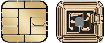
You can see it has the contact interface on one side, and on the other side it has a chip and an antenna. While you can use the CoM directly to make purchases, the antenna is very small, and it is tuned far from the target frequency (17-19MHz instead of the NFC standard 13.56MHz). To enable it to communicate with a reader, you need another, physically separate tuned circuit which I’ll call a “resonant repeater”. The resonant repeater has its own coil antenna and capacitor tuned to resonate near to the target frequency.
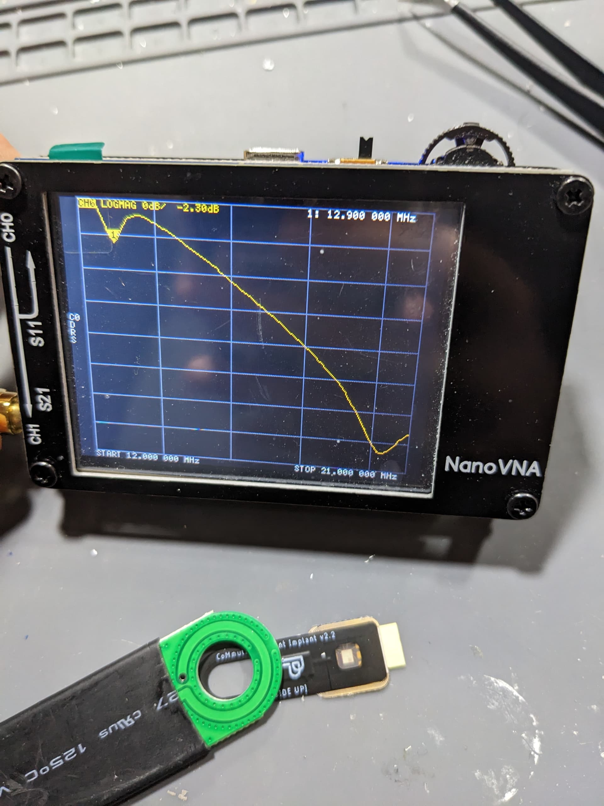
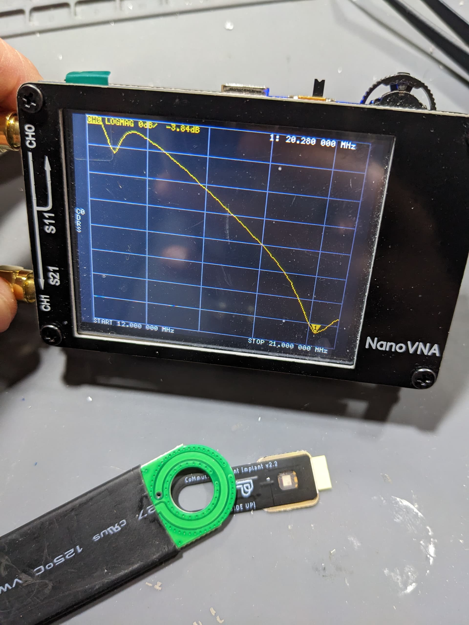
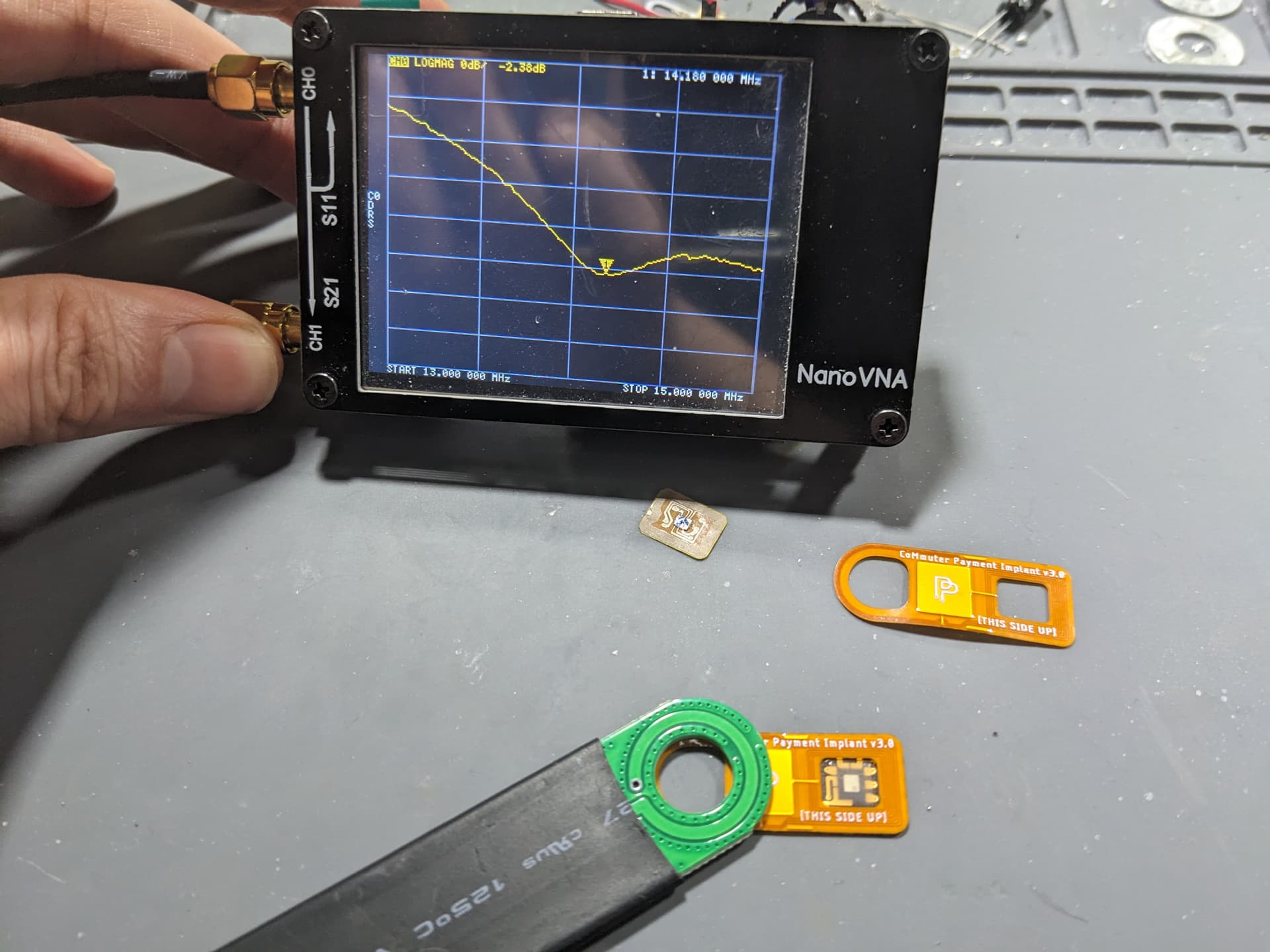
The two antennas (CoM and repeater) are placed physically against each other so that they mutually couple, but are electrically isolated from each other (separate pieces/board). Because of the resonant frequency range of the CoM module, you will want your resonant repeater to have a resonant frequency around 14MHz. I haven’t yet discovered the math to exactly map out the behavior, but when these mutually coupled circuits are placed near each other, you get two resonant peaks. One is slightly lower than the repeater’s resonant frequency, and one is higher than the CoM’s resonant frequency. You want the lower peak to be slightly above 13.56MHz.
To make the resonant repeater, you’ll need a coil antenna and a capacitor. You can hand wind a wire coil and solder on a discrete capacitor using the information from earlier posts in this thread. If you want to make a resonant repeater on a PCB using copper plates as the capacitor, you’ll need to do a bit of math. I use Wolfram Alpha to make it easier.
C = ε0 * εr * (A/d)

* ε0 (vacuum permittivity) = 8.8541878128⋅10−12 F/m
* εr (relative permittivity) = 3.4 [polyimide]
* A (area of plates): 1cm2 = 0.0001m2
* d (distance between plates): either 0.025mm or 0.012mm for PCBWay flex

Example:

(8.8541878128*(10^(-12)))*(3.4)*((0.0001)/(0.000025))

= (1.2041695425408) × (10^(-10))

Which is 120pF (pico-Farads)
Another important factor to consider is called “coupling factor” (k). To get the ideal coupling, the reader antenna and the tag antenna should be the same size, have a similar number of turns, and overlap completely. In an ideal coupling scenario, the resonant peak may be 14.5MHz.
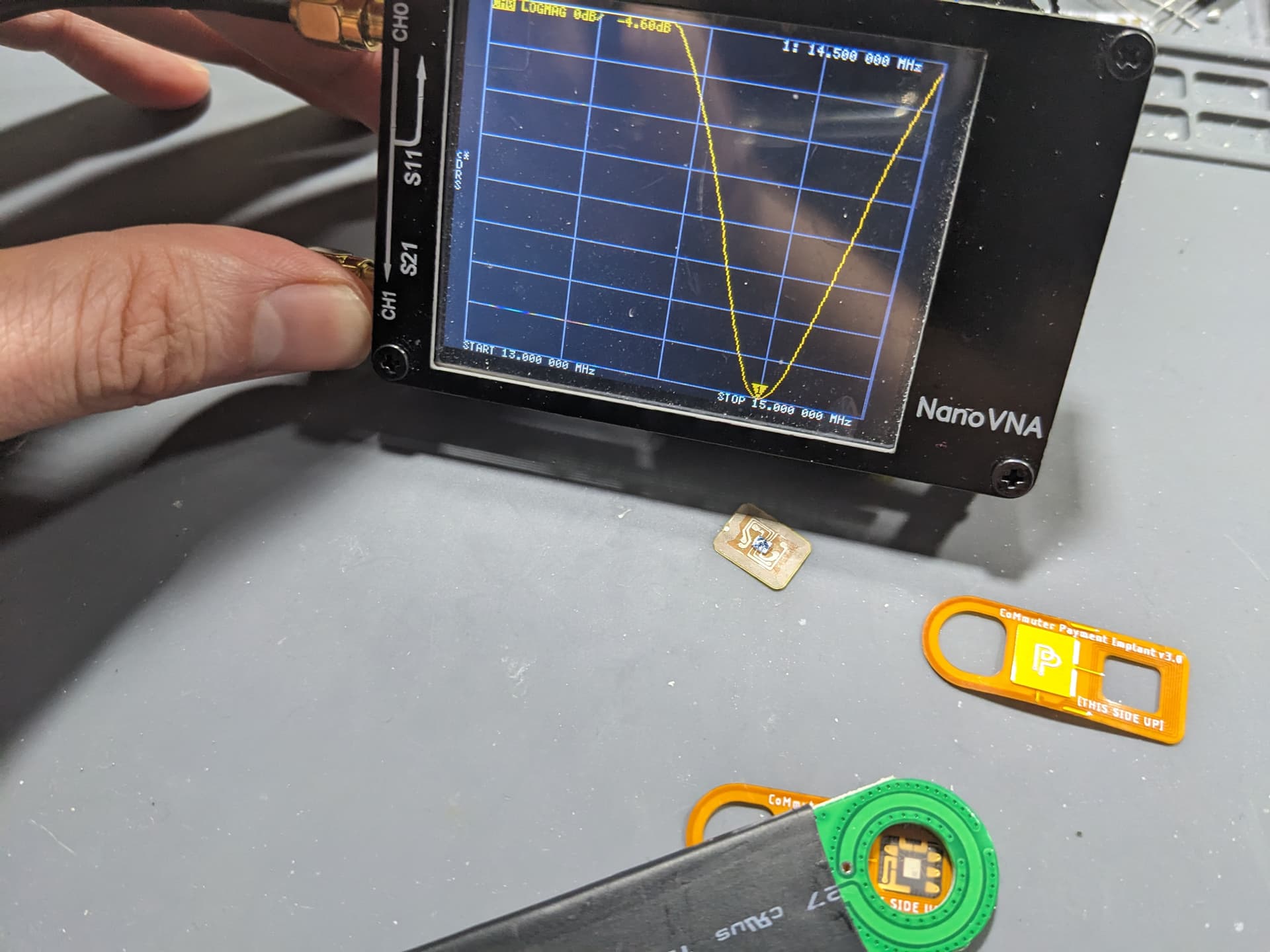
In less ideal coupling scenarios, the amplitude of the draw (amount of energy available to the tag) will decrease. Another important factor is that the resonant peak will change. Usually this manifests as the resonant peak becoming lower as the coupling degrades.
You will need to account for this when designing and testing your circuits. You want to make sure you have the ideal coupling on your measurement antenna to get accurate resonant peak values. You also want to plan your design around the intended coupling scenario. In this case there is a payment terminal with a much larger antenna, so the coupling factor will be poor, and the resonant peak will go down a few hundred kHz.