@amal I feel like I have seen you talk about an HF version of the DT LF antenna for the RDV4. Would you know anyone who could point me in the right direction for a coil that couples well with the HF implants?
Edit: or simply the full specs of the coil in the xLED so I can try simulate it with some software.
Well if you do actually want to get involved in this project or just hobbyist electronics I’m sure plenty of people (including myself with my hodge podge knowledge) would be more than happy to help out
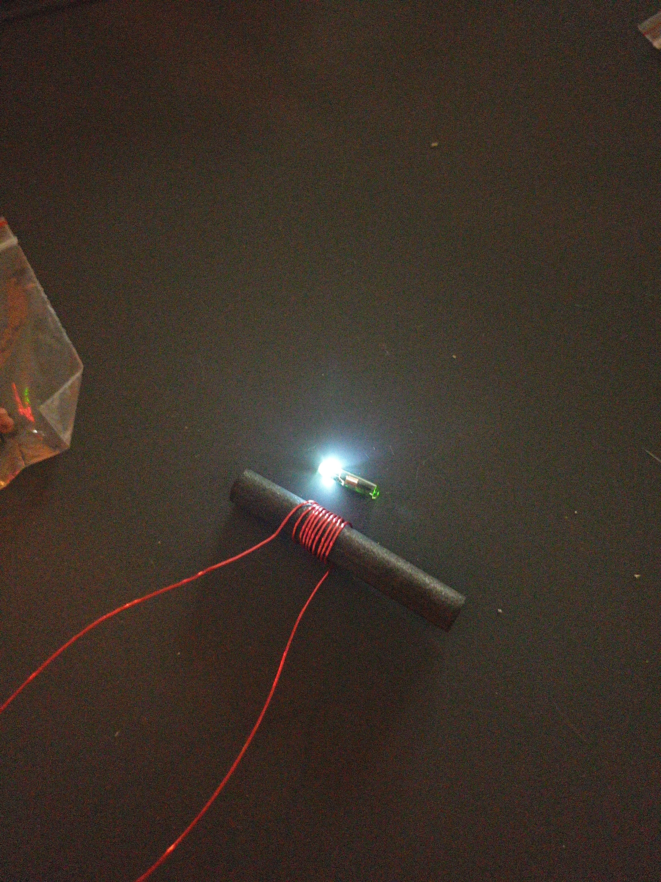
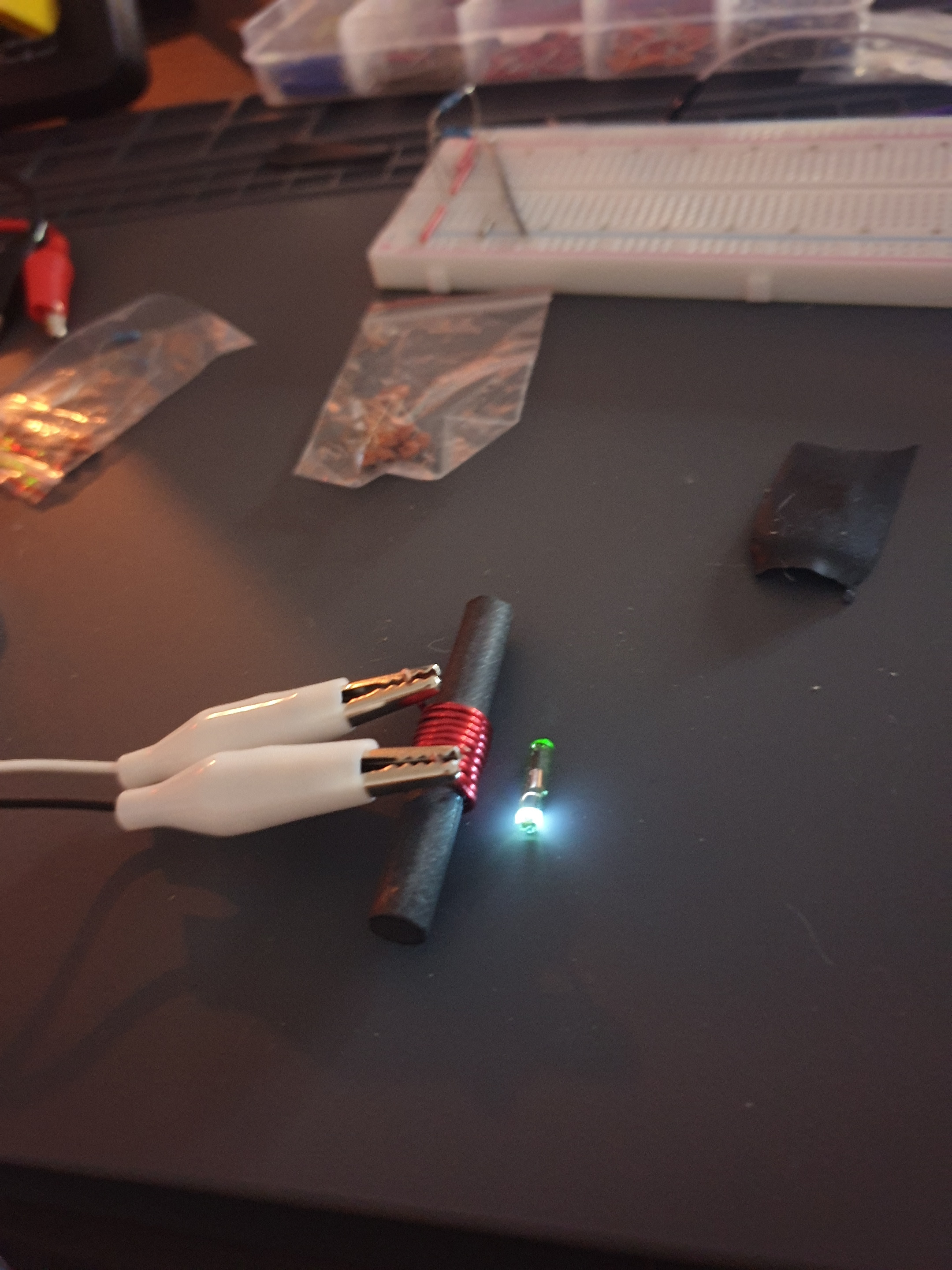
The air core coil will light the LED in the center because the magnetic flux is densest there. The ferrite core coil is closer to what we’re going to want. You can check out my last couple posts in the tragus wireless headphone thread to get some more details and links. Basically, the variables that increase field strength (B) are:
Current flow
Number of turns / length of coil
Permeability of core material
So I think we can try two avenues
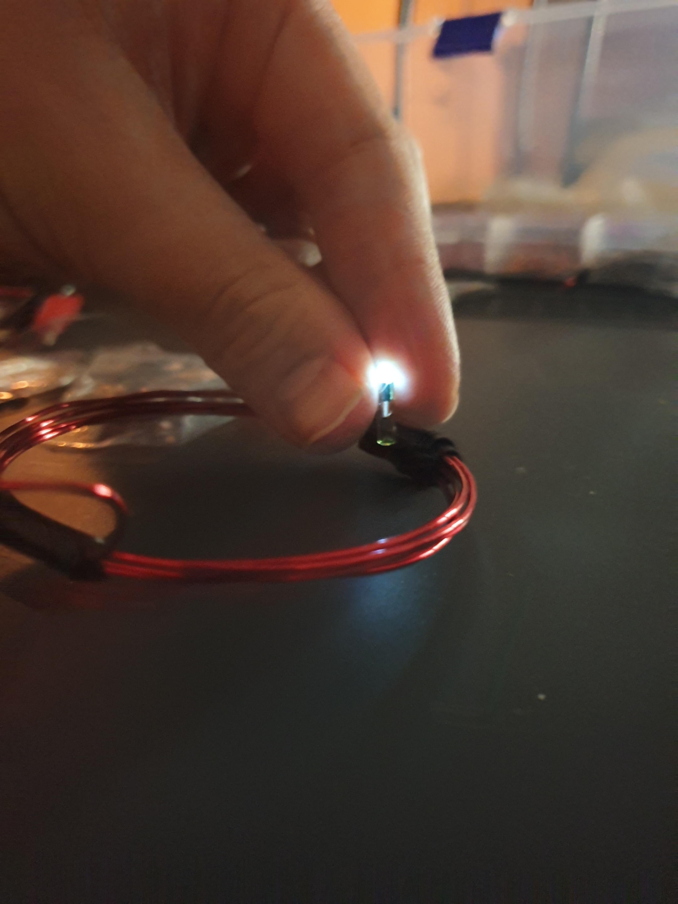
Air-core bracelet with max turns in minimum length and larger amount of current.
(That transistor can handle 40V so maybe we bump that up and run a few in parallel. Will require change to circuit)
Try a different core material. Small coil (not bracelet)
Really, I miss configured my variable power supply and over volted them a bit and let out the magic smoke. Although maybe that was overloading the gate.
My new variable power supply is weird it (at least on this circuit) always shows 0.0 A draw which seems wrong. Was going to test something else just to see if it’s like not broken and is just drawing under 0.1 A.
I’ll have a look into your suggestions some time later today
Mainly because it was easy I hooked a a signal generator (my multimeter has one) up to the big air coil I made. 125KHz square wave at 2.5v… powers the LF xLED in a multitude of positions.
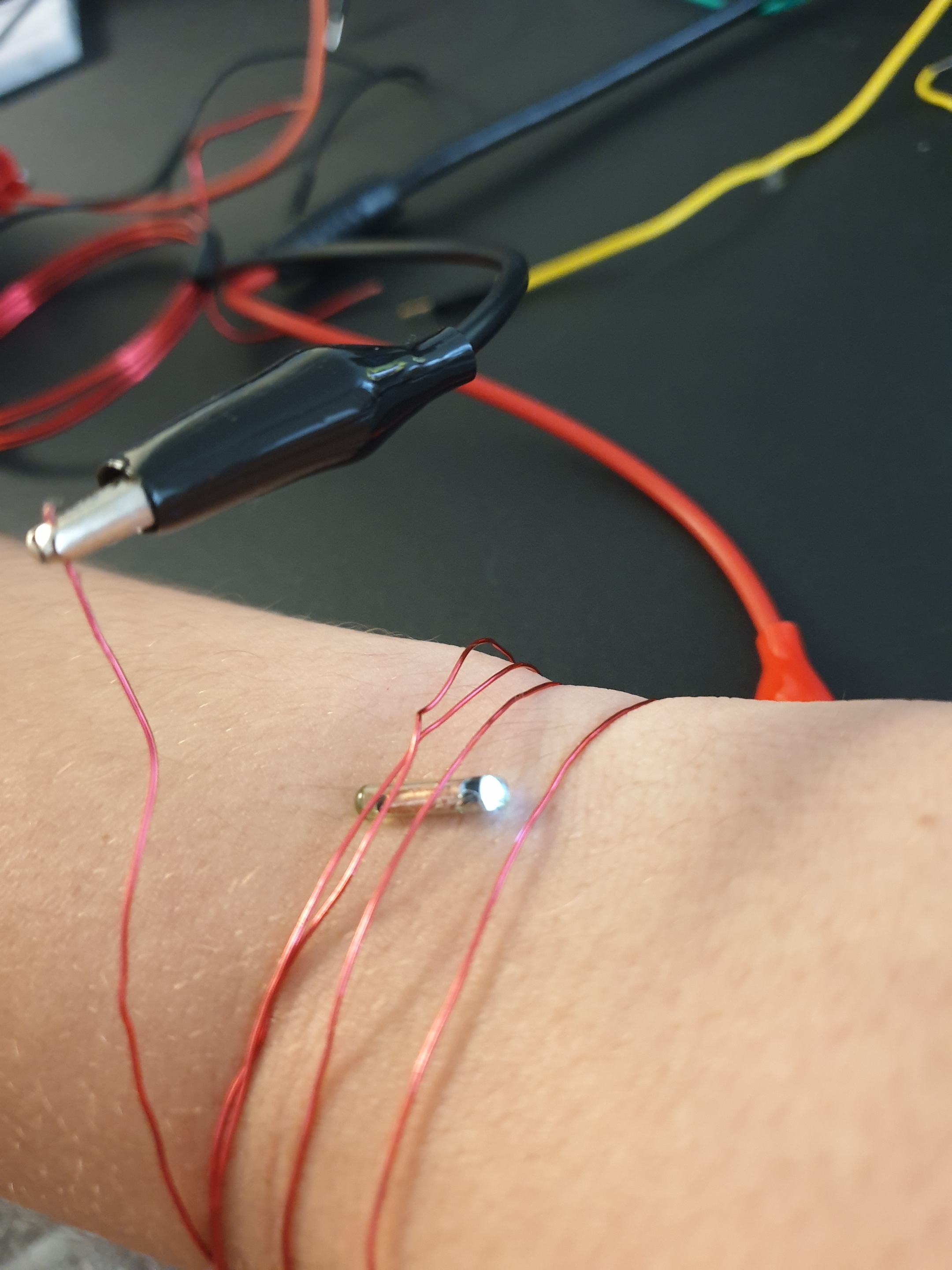
I still want to get the HF one working but I also definitely think I’ll try make a 125KHz one, see what range I can get.
I can post this in a new thread as to not derail this one if needed.
I know a lot of you have been trying to find a way to make a bracelet that will make the blinkys blink. I have been thinking of alternative ways to light up my arm. These are my ideas so far.
If any are blatantly wrong, let me know. (Still Learning, just making a shopping list for payday) I am just trying to come up with a good first project for me. (To go along with my KBR build)
Would it be possible to hook this to an external power supply? Not specifically this one,
But maybe this one also,
I may not be computer savvy, but I am art savvy (to a point) and I feel I could make it look alright for me to wear with some changes, like casting it in resin with maybe a few more led’s to light up, or just cast in resin with a basic design as to not detract from the xLED. Could also maybe use it to program a light show? Maybe even hook it to a mic for music induced light shows.
I wasn’t sure if I could hide it in something like this, but I would sew my own with raw denim likely.
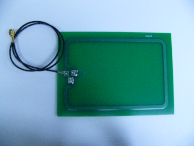
Also, unless I am misunderstanding it, could I not just cut the middle out of this one, and put it around the implant with it inside (like a picture frame)?
I know I could cast that to look nice in resin.
If this is too off subject, let me know and I will relocate it.
@Pilgrimsmaster posted an image (can’t remember what thread) with exactly that idea. His antenna came with the middle cut out already but there is nothing that would stop you from cutting the inside out yourself as long as you don’t cut the antenna trace. It’s just unused PCB.
Well actually it would not blink with the current design. It would just stay lit.
Hooking up power to a standard reader likely won’t work because it would not be trying to read, you would need a microcontroller like the Leonardo you linked, although there are plenty of smaller form factors. This would make the led blink whenever it tried to read it. But the main issue you would have is finding a module that can power the led without blocking it. Which is what we are trying to solve essentially
Hmm. I don’t remember much about this circuit, but you would either need to change some resistor values to bias the transistor differently, or you would change the properties of the load (coil) so that it will allow more current to flow. I think the coil has negligible resistance, though, so it’s probably just the biasing of the transistor that affects the maximum current. More saturation!
We went over this one in leeborg’s thread (no worries, there’s alot of information here). You wouldn’t be able to frame the xLED in the middle of that coil with the middle cut out because the xLED would need to be poking straight up out of your body. If you wanted to use that coil you would need to lay it directly over top of the xLED, which blocks it. That’s why we’re planning a bracelet coil, because the field lines are running parallel with your arm, just like the xLED would be under your skin.
Just to clarify, the PCBs are made of fiberglass, not silicon, and it has little to no affect on magnetic fields.


 (AFAIK)