Resonant Repeater Stickers

Thanks. I tried after reading your message, but can’t find an option to do it. I am sure if it is still open, or re-opens, someone will let me know…!

1 Like

Absolutely

I tried about 3 times, and there was an issue with the payment method, I wasn’t alone. but it obviously worked for some, maybe it was an international payment issue. :man_shrugging:

I know it fucked up Michelle’s accounting (And I did it 3 times to make it worse :wink:)

I’m not sure where Amal got to with it…

1 Like

Happened to me also so not an international thing

1 Like

I have 1 maybe 2 friends who are keen for a pay implant, but in Aus the only option is a CoM with a resonant repeater. @Satur9 are you still keen to get your designs working?

I opened up my heavily modded moto g pro today and the nfc mod is still there and working fine. It reminded me of this project though, I wish I could have a sticker for my next phone :crossed_fingers:

1 Like

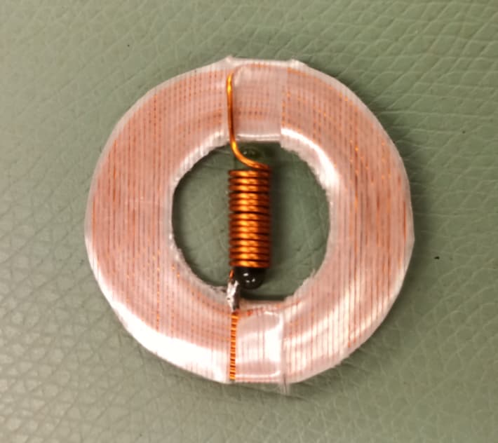
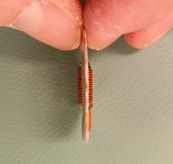
I actually made a few of those glassie boosters some time ago, and they work really well:


7 Likes

Yup. Still getting my money situation worked out, but it’s high on my priority list

Nice work! That’s some excellent range. You might even get better results if you measure the inductance and then add an appropriate capacitor. If you have access to an LCR meter or a VNA that would sort it right out.

1 Like

I might be able to get some extra contribution from them if that’s what you mean?

just making sure, I understand the principles

as cool as this is, (which is super cool btw)
this wouldn’t work for a glass tag, that’s already implanted right?
the booster coil needs to wrap fully around the tags coil to more or less couple the 2 fields?

Correct. This pair of coils is “coupling agnostic”: it’s basically one large planar coil with a smaller 3mm-diameter coil inside, with as many turns of magnet wire with as thick a wire gauge as possible. It itself doesn’t resonate or anything: the glassie inside does.

In short, it’s a transformer.

The two issues are:

  • Yes, you do need to slip the glassie inside the inner coil first, then encapsulate the whole device before implantation. This is not for an existing glassie that’s already implanted, that you want to boost. For that, you can make external repeater coils such as the one I use to boost the range of the payment implant in my finger:

    If this ever becomes a product, I envision it to be an option when you purchase an implant that only comes as a glassie: buy the glassie alone with its convenient injector, or buy it mounted into an encapsulated booster and have your installer scalpel you and dermal-elevator you to install it, if you’re not squeamish and you want the performance boost.

  • It’s very stiff because it’s 24 ga copper wire, and it should never flex anyway because the outer coil loops would rub against each other and eventually grind down the enamel and short out. So it’s something to encapsulate into some hard bio-compatible material that doesn’t exist yet. I believe Amal is toying with some sort of resin to create hard implants, but I don’t believe he has gotten anywhere with that yet.

So this is very much experimentation and proof of concept at this point. Although I do have an immediate need to implant one of my glassie boosters with a certain glassie inside, so Amal I formally volunteer to be a guinea pig for the first “hardie” you come up with :slight_smile:

right, I can follow how that works…

so how does the resonant repeater coil work? I kinda want to build one of those

The type I make, yes. You can get fancy and make it out of thinner wire and fewer turns, or PCB traces, in which case its own idiosyncrasies would start to impact the coupling of the glassie inside and you’d have to tune the pair of them for best performances. But if you stick to thick wire, essentially the more you throw at it, the better it works :slight_smile:

One caveat if you want to play with this: pay attention to how the coil transitions from the pickup coil to the radiator coil. In this case, it’s no issue because the pickup coil is planar, and the radiator is a coily coil orthogonal to the plane of the pickup coil.

But for something like the booster for my finger implant, which is in fact one small rectangular planar coil within another, larger one, for some reason they need to be coiled in opposition of one another (i.e. one needs to be coiled clockwise while the other needs to be coiled counterclockwise).

I don’t know why, common sense would dictate that they should work best if both coils turn in the same direction, but apparently the signal cancels out with this particular arrangement of coils for some reason.

In short, there’s a fair amount of black magic involved. But you can quickly come up with something that works surprisingly well without having to iterate through PCB designs for ages.

1 Like

Hmmm, that’s interesting. If both coplanar coils are wound in the same direction, it’s kind of the same as one larger coil as the inductors are cumulatively coupled in series. If they’re wound opposite directions then they’re differentially coupled. The current lags the voltage in the first coil, and that current induces a new field in the second coil ~90° out of phase of the first. Here’s my hypothesis. Sorry they’re a bit messy

In the cumulatively coupled scenario, the waveform becomes unrecognizable and the peaks shift so it is no longer 13.56MHz. In the differentially coupled scenario like you settled on, the amplitudes get a bit erratic, but the peaks are still in the correct place and it’s still 13.56MHz.

I can’t imagine what the responses look like to the reader :sweat_smile: it works though, and that’s all that matters.

As a matter of principal I don’t take money from people who aren’t directly participating in the creation of a project. Someone always ends up disappointed and I’d much rather have partners than customers. Like you or Miana could definitely contribute to the order, because I know you’re both interested and are engaged in the project. You can help ideate and design and test things. Your friends probably just want to: give money, get thing. I don’t jive well with that.

I suppose if enough people were interested Amal could contract me to do it for DT. I was just planning to do it myself though and share the design with everybody. Right now I’m financially recovering from the purchase of a CNC Pick and Place machine, but in a few weeks I’ll order some more boards to test out the onboard capacitors.

1 Like

What are we talking hundreds? Thousands? I wouldn’t mind getting in on a little piece of the smart people action. I have absolutely nothing to offer brain wise but cash wise I can be convinced.

1 Like

I’m sure you’re plenty smart enough. It’s more about drive. What I’m saying is that I don’t just accept people throwing money at a problem. I prefer to work with grinders not observers.

1 Like

That makes sense

I think theres an app for that :smirk:

4 Likes

I’ve got another friend who’s keen for a CoM conversion (that’s 3 now), you don’t want to take funding from non-grinders but what about pre-orders? If it makes you feel better then you could give the money back if you’re not happy with the end result I guess?
If not we could do a video call sometime and I’ll see if I can help out with the design

We could do a call if you want. I’m on the discord, which would make that easy. I think we’re pretty far off in timezones though. It would probably have to be morning for you, night for me. DM me if you want to arrange something.

I was just waiting until I have a bit more scratch before I do the design. If you really wanted to expedite that process then I guess we could work something out.