Tragus Implants and You (but also me)

Cochlear implants deliver electricity directly to the cochlea using electrodes they do not rely on mechanical vibration to deliver sound but the sound delivered using this menthod cannot match the natural sound because there are millions of hair cells in cochlea which produce a range of different voltages the technology today is not able to produce that range of different voltages
But i am talking about putting a Maxum magnetic implant in a person with normal hearing I don’t think it will cause hearing loss if there is no sepsis or trauma (extremely rare)
This magnetic implant directly vibrates the stapes bone in the middle ear producing crisp and clear sound (clearer than even the natural sound which we hear)

Okay that makes sense, you mentioned Maxum earlier. You’ve just been all over the place with suggestions so I got confused. So here’s a picture of the Maxum system.

The implant itself is actually a magnet. The “wearable” part is a battery powered unit you insert in your ear canal that has a DSP to translate audio in the environment into magnetic pulses that move the magnet implant. That’s cool, and could work for what you’re suggesting, but

  1. The default wearable unit only supports environmental audio, it doesn’t appear to have Bluetooth or the ability to support audio from any other sources. So what’s the plan, to design your own wearable part with more features?

  2. if you have to get invasive surgery and stick a bit of electronics in your ear canal why not just get True Wireless earbuds?

The plan is to use inductive neckloop or an implanted inductive loop which will receive Bluetooth or UHF signals to deliver it to the magnet implanted in middle ear
The point is to make it covert make it undetectable no wireless earbud can do that

The Maxum magnet seems very directional, that’s why it has that wire loop holding it to that specific bone. A neckloop likely won’t stimulate it the same way. Also how will we go about getting someone to do the surgery, cause if we can figure that out we have options, doesn’t necessarily need to be Maxum.

No
it’s tied to stapes bone because stapes bone is a part of the chain of bones through which vibration travels from tympanic membrane (eardrum) to the oval window and then to otolith (a fluid in cochlea) which stimulates the hair like structures to produce voltages which stimulates the auditory nerves which deliver this information to hearing area of brain and brain produces this hearing sensation
Cochlear implants are very different because they directly deliver electricity to cochlea using electrodes
Sensation of hearing can be produced by directly stimulating the auditory area of brain as well but that technology is still in development

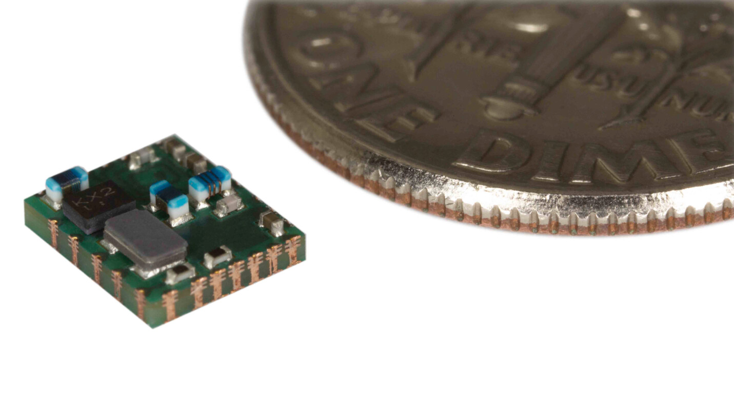
MICS-Band RF Miniaturized Standard Implant Module (MiniSIM)

The ZL70323 implantable radio module is a high-performance, easy-to-use RF module based on the ZL70103 MICS-band transceiver IC. The module is small and is designed to provide good performance while consuming very little power. The ZL70323 RF module integrates all the circuitry and functionality required to deploy a complete radio solution for implantable applications. This allows the circuit complexity to be reduced to placing one single package on your implantable application board.
https://www.microsemi.com/existing-parts/parts/137900

Nice find. Doesn’t look like it’s available for purchase but maybe I can reach out to my microchip rep. Unfortunately it only supports 200kbps data rates which is not nearly enough for audio. It needs to be that way so that it can penetrate the body because of the dielectric properties of flesh I mentioned earlier.

Batteries used in pacemakers last lifelong if we can access those batteries it can be used to power these devices apart from that we also need to perfect the wireless charging technology for implants.
Nobody thought that it’s possible to make a titanium encased neodymium magnet like titan

Yeah, the lithium iodide batteries used in pacemakers are nice. They do last a lifetime but it’s because pacemakers only draw a few microwatts, not the full watts that a inductively coupled audio transmitter would draw. Also, lithium iodide batteries are primary cells, which means they are not rechargable.

I don’t know if you saw the updates in the bodybytes thread, but I made a pretty compact Qi receiver that we intend to use in an implant. It would also be trivial to use the NTAG I2C Plus or NTAG 5 chips we already use in implants to charge a small battery with NFC

I want the same future as you, but I want to be realistic and more importantly safe so that more people can join us. We need to think very carefully and outline a plan if we plan to use implanted batteries. Others have tried and failed.

But we need cooperation from surgeons and the companies which make implantable devices.
The implants can be tested in animals to see whether it fails or not before human trials.
I came to know about these audio sunglasses my plan is to remove the speakers and put a coil which will vibrate the magnet implanted in middle ear

We can also design glasses frames ourselves with inbuilt Bluetooth audio amplifier and wireless charging system.
Someone who owns a good 3d printer should try

Ok, wire arrived, tests are concluded.
I ordered 0,3mm (~28 gauge) enameled copper wire. From that, I would 3 coils:
2x 20 windings, ~13m, 3,2Ω each
1x 8 windings, ~5m, 1,6Ω

The first tests were with the Hero. It needs to be at max volume, which means that it outputs 2,5V.

  1. only the 8x coil, so 1,6Ω. The Hero put out 1,4A, so ~4W total. The sound was very quiet.
  2. only the 20x coil, so 3,2Ω. The Hero put out 0,6-0,8A, so ~2W total. The sound was very quiet too, but possibly slightly better than the 8x coil. Not sure, both very hard to hear.
  3. both 20x coils parallel, so 1,6Ω total. The Hero put out 1,4A, so ~4W total. The sound was basically imperceptible.
    I wanted to test this theory with that configuration.

2 wires in parallel is a lot less that “many”, but since the result with 2 parallel coils was so much worse than just one, even though the amperage was double, i am not convinced that this approach is usable here.

  1. 8x coil and 20x coil parallell, so ~1Ω total. The Hero put out 2,6A, so ~6,5W total. Best result by far, but still fairly quiet.

I also still had this other 50W amp, so i tested that too. With the 20x coil i got 2,5A at 7V, so 17,5W. Volume was quite good, almost at a usable level. The wire got seriously hot though. I couldnt test the 8x coil, its 1,6Ω resistance was to low.

What i gather from this is:
Amperage is king. Volume definetly scales with amperage and thus inversely with resistance. Thats quite logical, the magnetic field strength (not sure if thats the word, not a native speaker) scales linearly with amperage. My guess is that we will need around 5A to get a decent volume. That unfortunately also means heat.
Not quite sure how voltage plays into this.On the 50W amp, as you turn up the volume, voltage and amperage go up equally. So maybe more voltage = more better? I only have 2 points of data that are not independant from the amperage, so i cant really draw any conclusions. @Satur9 , what is your opinion on this?
The number of windings also seems to positively impact volume. I need to order thicker wire to get a coil with more windings, but at the same resistance. But since we are working with AC here, more windings also increase the reactance (never heard that word before, i mean the imaginary part of the resistance) which again means lower current? Just guessing, feel free to correct me.

In the end, i believe it all comes down to power, which is annoying, because power means bigger electronics, faster battery drain, more heat etc. The “coil around the neck”-tests just constantly show that it is impractical. As much as i want to get it to work, I dont see how. Any ideas on how to proceed?

So I think by parallel you’re implying that you made two coils and just held them next to each other. That would not produce the desired result and if you accidentally attached one clockwise and the other counter-clockwise they would actually cancel each other out. What I meant was that you take many lengths of wire, twist them together into one thick wire, twist that whole thick wire to form a larger neck coil, then connect the ends of that thicker wire to the Hero as one big coil. This would be just like a standard stranded wire, but with the benefit of each strand being individually isolated forming parallel inductors. You already did a bunch of work and used resources, so if you want me to test it out I might be able to.

I explained this earlier in the thread, but there’s 4 factors that affect the amount of magnetic “flux density” ( B ) produced by a coil. Here’s a hyperphysics article if you want to dive in. Here’s the equation:

Capture

B = flux density (value we want to increase)
μ = magnetic permability (in this case it’s an air core, but in earlier posts I changed my core to mu metal to increase the strength)
N = number of turns
L = length of coil
I = current flow

  • So N is the easiest to increase, because we just add more turns and it will make a huge difference.
  • I or current is easy to increase to a point, but like you mentioned heat and component size are limiting factors.
  • μ can only be increased if we change the core material. It doesn’t need to fill the whole interior of the loop, just a few millimeters near to the coil turns where the flux is concentrated.
  • L we want to minimize, but a thin neck loop is pretty much as thin as we can get.

The relationship between Voltage, Current, Resistance, and Power is easy to understand if you check out Ohm’s Law

dccircuits-dcp4

Pretty much. I placed both around my neck.

I wouldnt even have thought about that, but now that you mention it…
Thank you btw for your continued presence here in this project, your practical experience really makes a difference.

The problem that i see is how to keep the resistance at the required level. The Hero needs at least 1,5ohm, the 50W-amp at least 3ohm. Assuming 1,5ohm, you would have to take strands with a length of 5m times the total number of strands, to counter the resistance loss by putting them in parallel. That would require handling potentially hundrets of meters of wire or really thin wire to up the specific resistance. Also, the amount of work would be insane. Am i just thinking to complex?

We can only really influence 2, I and N. L is pretty much minimal, mu would require a mu-Metal sleeve or something like that. Correct so far?
Amperage helps, but ist limited by several factors.
I probably underestimated the influence of the number of windings, because hearing a meaningful difference between two very quiet noises is difficult.
If i take a few coils with say 60 windings (probably ~10 ohms) and put them in parallel to reduce the total resistance, keeping in mind the direction, would that be a valid approach?

1 Like

You may be right. If you have 28AWG wire (0.32mm diameter) it’s about 0.21 ohms per meter. If you do many in parallel it would reduce significantly, but there might be more to this than we expect because impedance is not just DC resistance, it involves the inductive and capacitive reactance which would be a major player in a weird fucking coil like that. I would have just wound a 2-3 meter coil like I suggested and tried it on the amplifier to see what happened. It probably has an overcurrent shutoff. It’s your call though. I’ve just tried everything else and we’re not even halfway to useable so I figured we mine as well go crazy.

Yup that could work. Just make sure they’re all aligned in the same rotational direction (CW or CCW).

I’ll try both in the coming days.

Is there any easy way to remove the enamel from the wire? Previously, i had to scrape this thin wire from all sides with scissors. Heat (soldering iron) is supposed to work, but at 300°C nothing happened yet and if i go any higher, my flux just burns away with a fair amount of smoke.

Yeah, the strategy is to properly clean your iron tip pretty vigorously so it shines, then put a small bead of solder on there (tinning). Have a clamp or crocodile clip hold the wire in the air. Press the iron tip to the side of the wire tip, making sure the flat face of the soldering iron tip is oriented to get the maximum surface area in contact with the wire. Hold it there for 2-3 seconds, then slowly poke at the iron tip/wire tip with your solder adding small amounts. Adding solder while heating the wire also adds flux (if the solder is rosin core) which helps the solder bead flow and form around the wire tip. Once the wire tip has been completely absorbed by the solder blob, run it up and down the length slowly, adding a bit more solder if it starts to drag. You’ll strip the urethane onto the surface of the solder bead and you can pull it away.

From the rest of my wire i got 4 50-turn coils, each with 7,3Ω. Putting all three in parallel results in 200 turns and 1,8Ω.
Btw, is it windings or turns?

Each turn is about 60cm, hand for scale.

Because the Hero can tolerate a slightly lower resistance, i added a 20-turn-coil from before, so 220 turns (4x50 and 1x20 in parallel) and 1,2Ω.

This time, i made sure that all coils were “clockwise”.

All the A/B-wires were connected to the +/- Terminal respectively. The A-wires always went to the left, the B-wires always to the right.

The sound was the best so far, but not that much better as you would expect from going from 20 turns to 220. Without a way to get actual numbers for the volume/ magnetic field strength, the coils are fairly hard to compare.

My phone has a magnetometer, so i gave that a shot.
The base reading is 67uT.
220 turns: 120-140uT, spikes to ~200 uT.
50 turns: 40-60uT, spikes to 80-100 uT.
20 turns: about the same as 50 turns, maybe 10-15 uT lower

I’d say that the built-in sensor isnt the proper tool for this job.

The coils-in-parallel-approach certainly works, but not as well as theory would suggest.
@Satur9 Where did you get that idea to twist several wires from? Personal experience or some research piece …?

Next I would probably test a single coil with ~200 turns. According to the wire resistance calculator, that requires 1,65mm wire, which i cant get from ebay, is to stiff to handle and to bulky in general.

What influence does the voltage have on the magnetic field?
Now that i have to order new wire, are there any other configurations that you would think are helpful to test?

I got it from a coil manufacturer that Amal and I are testing out. They have coils like that and they have surprisingly good read range. It’s a good strategy to maximize inductance while minimizing resistance.

Voltage itself has no effect on the magnetic field. Having more voltage and/or less resistance increases the amount of current flowing, which does effect the strength of the field as you saw in that equation earlier.

High inductance coils will have more resistance the higher the frequency, and less resistance the lower the frequency. High capacitance coils will have less resistance the higher the frequency, and more resistance the lower the frequency. Capacitance also increases as voltage goes up, because the skin depth increases the higher the voltage with AC. There’s also back EMF and impedance mismatch causing reflections to consider.

It’s all very complicated, just try things based on the variables you know and can control, and see if you can get relative performance measurements like you have been doing. If you’re ordering stuff you could try and get some thin ferrite sheets and wrap them around your coil once it’s constructed. That’s one thing I didn’t try which will significantly increase the permeability.

1 Like

I discovered a small flaw in my previous setup. The 20x coil i put in parallel with the 4 50x coils has a lower resistance than the 50x coils, so it “steals” current from the coils with a higher resistance. To get an even current distribution and thus a higher current through the coils with more turns i added the other 20x and 8x in series with the 20x coil so i now have basically 5 50x coils in parallel.
That already got slightly better results, the phone sensor regularly spiked over 400 uT.

Is there any not-expensive way of more or less accurately measuring the field strength? Most teslameters i found are rather expensive.

Also, does the percieved volume scale linearly with the field strength or logarithmically like on the decibel scale?

1 Like

Yeah I thought that’s what you said before but I wasn’t sure I understood correctly.

Your ears are probably best. The perceived volume will scale logarithmically because that’s how ears work. Ultimately it doesn’t matter what the meter says because you’re trying to create a subjective user experience