So let me start out by saying that I’ve been approaching this from an engineering standpoint. The difficulty is that the behavior of fields is pretty high order stuff. Locating and understanding the actual math behind it is rather difficult. That being said, we can feel this problem out and verify by experimentation.
I’ve seen commercial units advertised to help cheat on tests. They use a 9V battery which supposedly lasts about 3hrs. They have a necklace coil. The issue is that those units really only work when the tiny magnet is against your eardrum, so we’re not going to get the same results with a tragus implant because of all the fleshy padding muffling the sound.
Personally, I don’t think think Rich Lee got very good performance out of his concealed necklace unit, and that was using an 18V power source (two 9V in series) and a pretty sizable amp. He might have pulled off a very low mosquito buzz volume level. This was adequate for his purposes, but I want to be able to hear music and sounds with higher volume and fidelity. We’re going to have to get creative about the design. So far I have tried the following:
-----Amplifiers-----
This 3W Bluethooth Amplifier
Worked well, but the Pk-Pk amplitude of the output was 1.1V, which was very weak with higher resistance coils.
This 160W digital amplifier
Has worked out very well. The Pk-Pk amplitude is directly related to the DC power source, which can be anywhere 8-26V. I’ve been using a DC power supply to run it at 18V.
-----Coils-----
-
Cannibalized voice coil
I took this from an existing speaker. It worked pretty well, but was only perceptible up to 3cm away. Best results when the axis of symmetry was pointing toward my ear canal (perpendicular to the poles of the magnet).
Specs: Diameter = 13.8mm, Height = 3mm, Inductance = 59μH, DC Resistance = 9Ω -
Self supported copper coil
For the first try I used 7 turns of 18AWG enameled copper wire. Worked terribly and I have since dismantled it so no pics. -
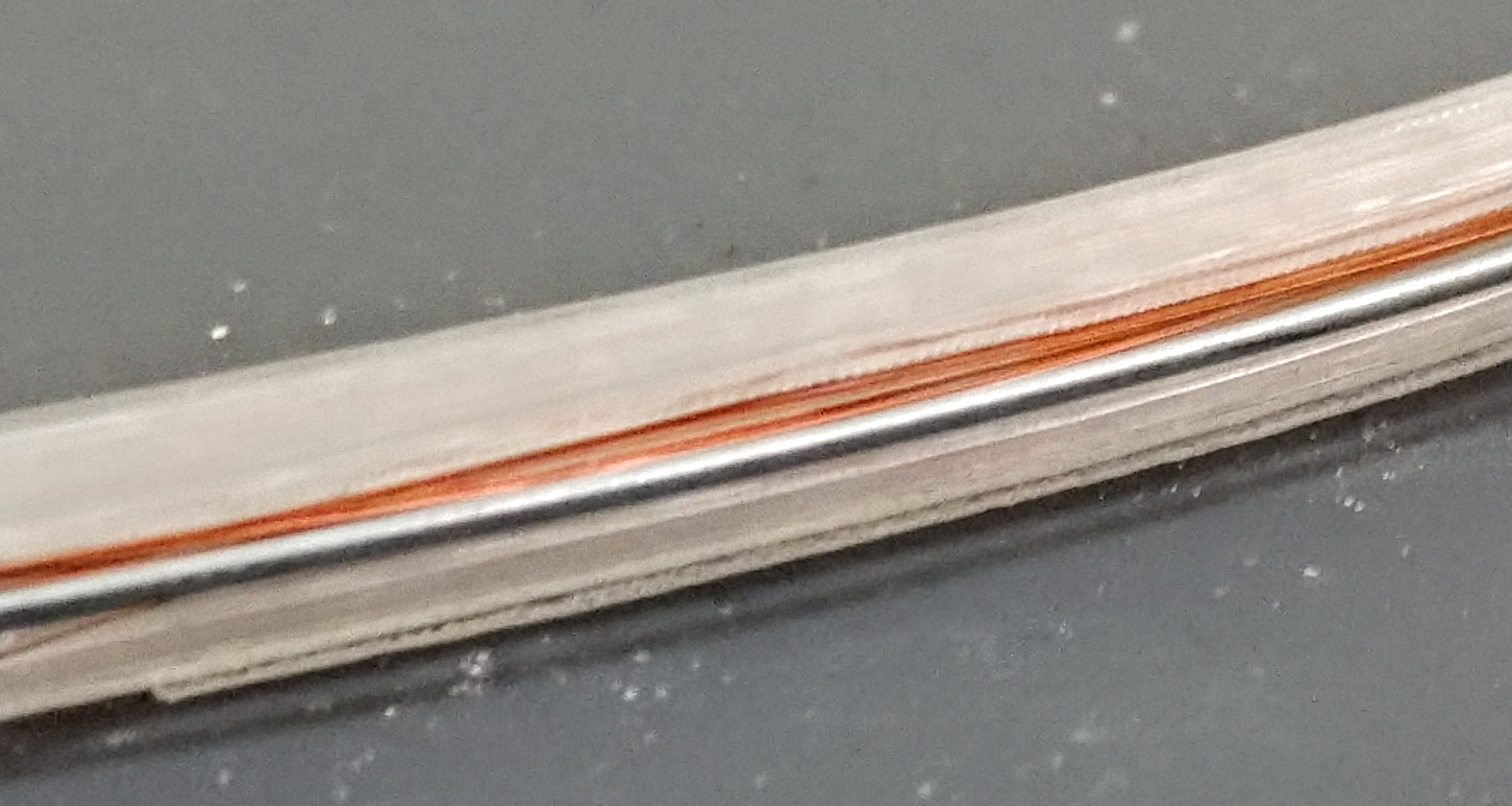
3D printed coil form
Started with 38AWG enameled copper wire so that I could achieve more windings in a smaller space. I got poor results with this coil, but I noticed that when I held my magnet implant againts the copper things improved. Decided to rewind it with some 18AWG steel wire in there and got slightly better range/fidelity.
Specs: Copper Gauge = 38AWG, Coil Width = 16.5cm, Coil Height = 20cm, Inductance = 51μH, DC Resistance = 17.6Ω -
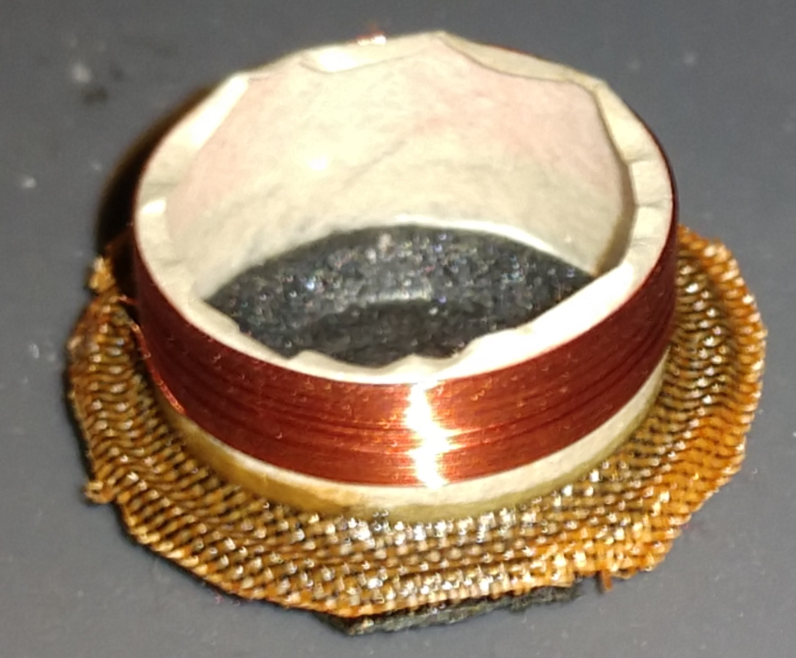
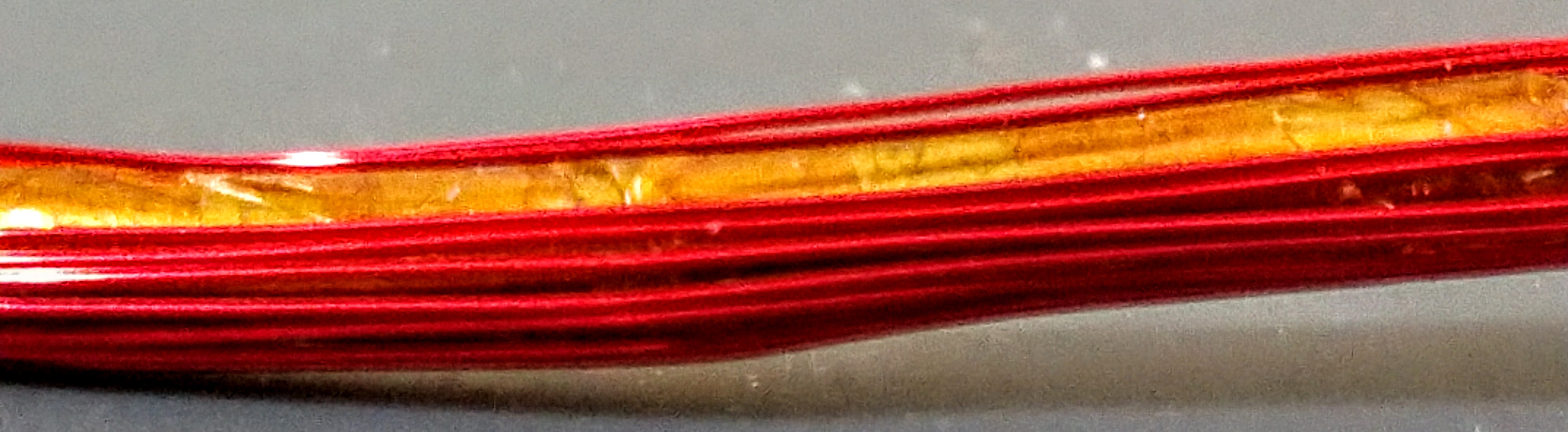
Steel coil form
These tests led me to try a thick (~3mm OD) steel ring as the coil form. I wrapped the ring in kapton tape to provide a sticky base for the copper to adhere to. I used a middling gauge copper this time to cut down on the resistance. This worked, but not significantly better than the 3D printed coil form. I might try this again with more windings, it was just so labor intensive I gave up early.
Specs: Copper Gauge = 28AWG, Coil Width = 16.5cm, Coil Height = 20cm, Inductance = 76.5μH, DC Resistance = 1.9Ω -
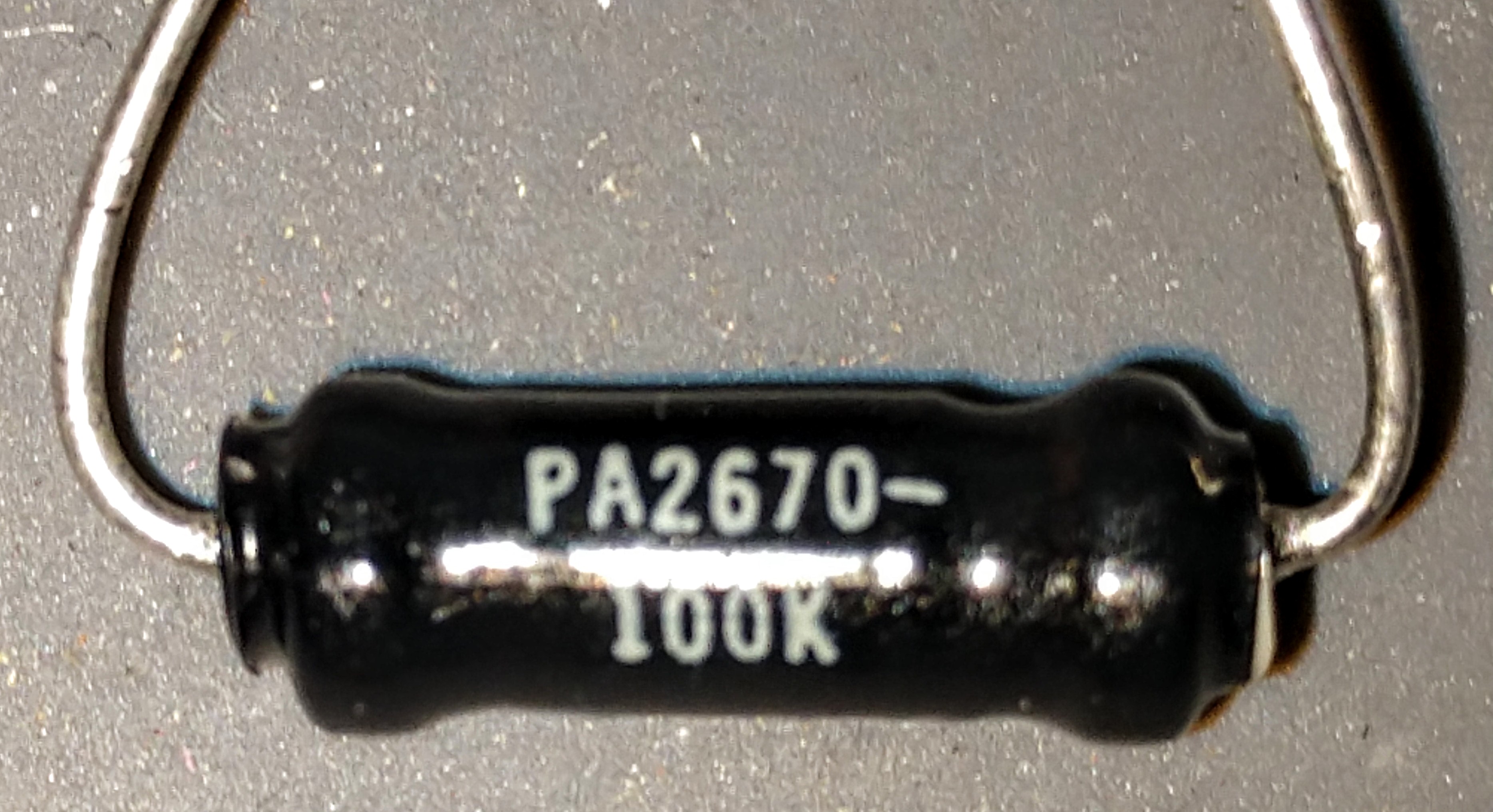
Discreet Inductor
Given that the large diameter coil necklaces don’t seem to work at a distance of more than a few cm, I decided to try other coil shapes. I used this discreet inductor the other day. It is 100μH, and has a DC Resistance of less than 1Ω. It worked okay, but got pretty hot. I’m going to do more testing.
I’m going to keep trying other things, but I pretty much think we have to do a complete redesign, or do a hat-brim coil like you mentioned. One important note when designing the coils is that DC Resistance is not the whole story when it comes to how much current the coil is going to pull from the amplifier. What you really need is Impedance at the target frequency.