xEM access controller for garage door question

I guess my question is why couldn’t you bypass the first relay? They share a ground, keep 86 and 87 the same and put the signal from the xAC directly to 30 of the second relay.

2 Likes

Read my comment :wink:

Thanks

2 Likes

I still completely don’t understand the point of the 2nd relay XD

It looks to me like the circuit as @Steven1727 drew it is dumping 12v into the button which seems like a terrible idea to me, since it’s doubtful something that tiny is running much more than 5V, but would probably still make the door open.

I’m not sure why you wouldn’t take xEM AC signal to a diode with the white stripe side to 86 Coil Control, tie 85 coil ground to xEM AC ground and then throw the two sides of the button on NO and common 30 and 87.

1 Like

When @ODaily and @Compgeek were helping me trouble shoot it that night we couldn’t get it to work that way… Something with the data wires… Then we figured out the data wires issue and we came to the conclusion that I needed to solder some wires to the button. A friend of mine came over a few days later and helped me solder the wires. When that happened and we hooked it up that way it did not work. The relay would not even click. After trying for literally about 3 hours this was the only thing we could get to work.

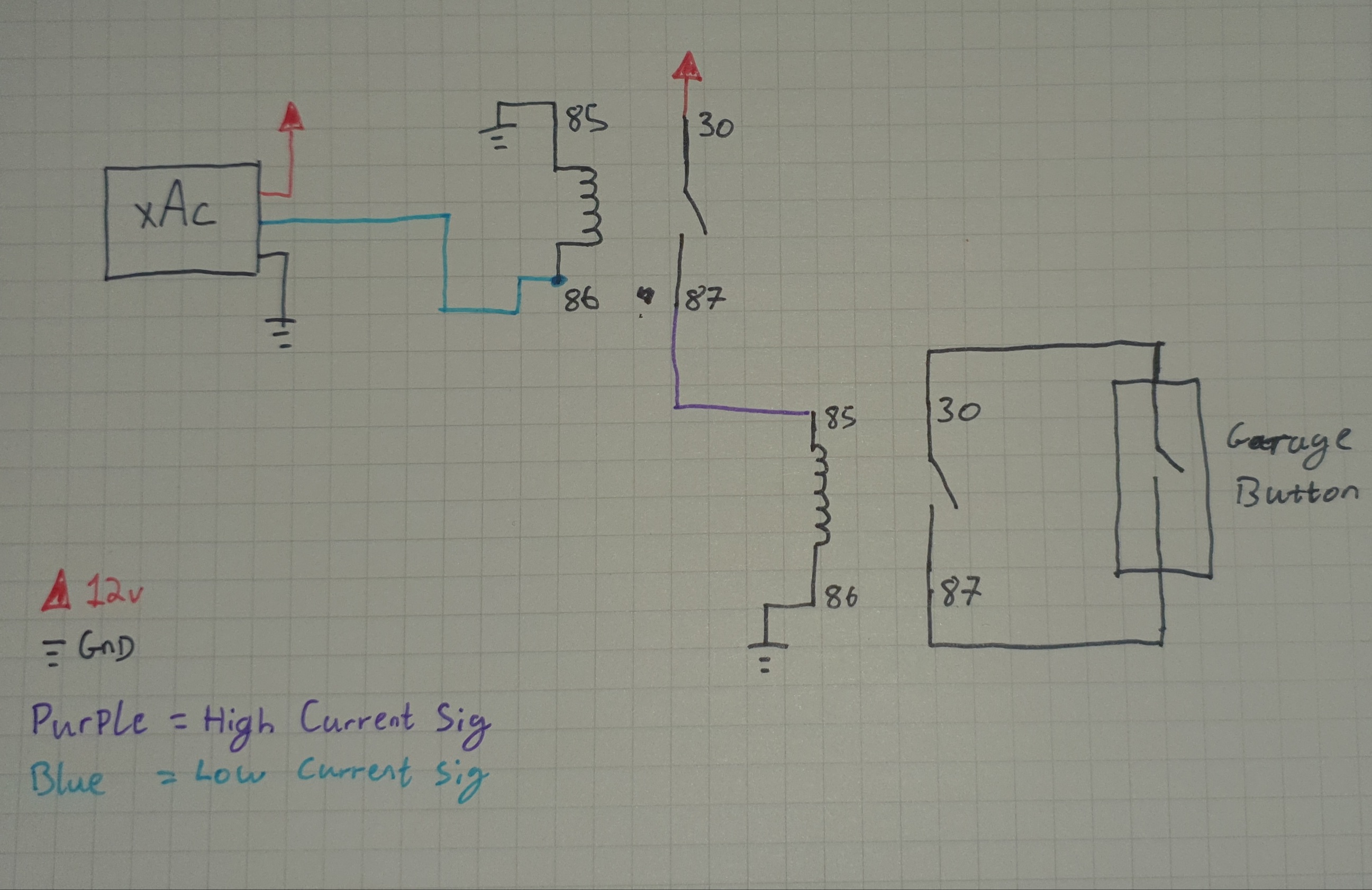
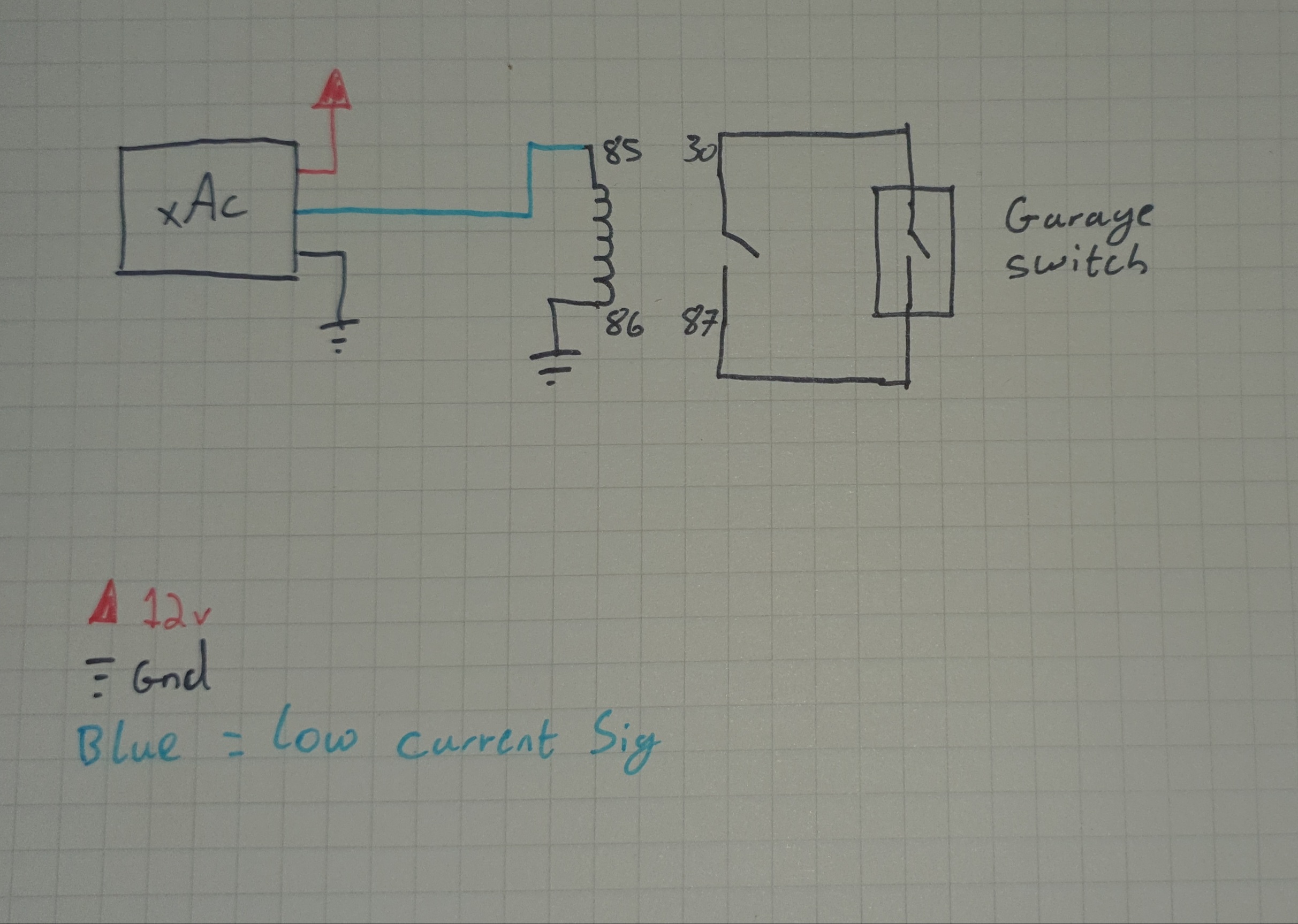
Right the 12v output of the xAC isn’t particularly useful to use, you drive the first relay using that to drive a higher power relay.

I personally though that the reason for 2 was to not put too much load on the output of the xAC.

Both of the circuits I’ve drawn are functionally identical.

4 Likes

After looking at it, drawing it and then thinking way too hard, I’ve determined it has to be wired how you drew it @Devilclarke since how @Steven1727 drew it would just be dumping 12v directly to an open button and wouldn’t actually do anything.

1 Like

Okay… My bad I just went outside to take a picture to “prove y’all wrong”. BUT I proved myself wrong lol my dyslexic ass flipped the posts and numbers lmao… The garage door wires are connected to 87 and 30 on the second relay. :man_facepalming:

3 Likes

Phew, that makes infinitely more sense, I was starting to doubt physics for a minute XD

2 Likes

dyslexia is my reason for drawing shit!

3 Likes

It helps when you don’t flip your wires :rofl:

3 Likes

did you run out of crayon colours :wink:

2 Likes

Nope orange and yellow were still available :laughing: But I am going to redraw it with the diode and correct way lol

3 Likes

You want me to add them to my drawings to?

All this is a pretty good example of why I wanted you to draw it in the first place. You learn what you never thought to ask about. IE, wait, WTF did I run this wire for? :roll_eyes:

You don’t need that second relay. Chances are you accidentally solved a problem when you put it in. Like a bad / loose connection or something.

That’s basically what Devilclarke was saying.

The way that circuit is designed would be useful if you wanted to run a big old honking load. Like a full size automotive starter motor. Relay 1 would be the standard little black relays you are already using, and relay two would be a heavy duty starter solenoid relay. Basically just for if the xAC was too light duty to run your super heavy duty relay directly.

I hate it when that happens. But… at least you got it right, and learned something in the process.

4 Likes

Tell you what I’ll redraw my single relay drawing with both diodes in and @Steven1727 you can reclaim one of the relays :smiley:

3 Likes

Microsoft Paint RULES!

I also added a place for a generic capacitor if you want to do that later.
IT MUST BE AFTER THE DIODE!

This will hold the button for a brief period of time, but will also help prevent getting a rapid on-off-on-off-on-off-on-off condition when you’re right at the edge of read range.

3 Likes

Make sure it’s a fat one, though. Like 10uF or more.

Also @ODaily, wouldn’t you want the flyback diode in parallel with the coil, not in series with it?

1 Like

Right here we go,

2 diodes, 1 protects the xAC the other helps suppress emf when the relay turns off.

I included the capacitor, this is optional. It will keep the relay on for a brief amount of time after the tag has scanned. (Needs to be big think 50uF+ 15v rated minimum)

As stated earlier only one relay is needed unless you need to drive a very large load.

EDIT: Looks like everyone wanted a go :sweat_smile:

6 Likes

Devilclarke, please forgive me for this, but I made a modification. For a non electrician it’s not intuitive what is, and what is not, inside the relay. So… I put a purple box around everything that is INSIDE the relay.

Once again, please forgive me butchering your image, just trying to help out those who don’t read this the way an electrician would.

3 Likes