xEM access controller for garage door question

You want me to add them to my drawings to?

All this is a pretty good example of why I wanted you to draw it in the first place. You learn what you never thought to ask about. IE, wait, WTF did I run this wire for? :roll_eyes:

You donā€™t need that second relay. Chances are you accidentally solved a problem when you put it in. Like a bad / loose connection or something.

Thatā€™s basically what Devilclarke was saying.

The way that circuit is designed would be useful if you wanted to run a big old honking load. Like a full size automotive starter motor. Relay 1 would be the standard little black relays you are already using, and relay two would be a heavy duty starter solenoid relay. Basically just for if the xAC was too light duty to run your super heavy duty relay directly.

I hate it when that happens. Butā€¦ at least you got it right, and learned something in the process.

4 Likes

Tell you what Iā€™ll redraw my single relay drawing with both diodes in and @Steven1727 you can reclaim one of the relays :smiley:

3 Likes

Microsoft Paint RULES!

I also added a place for a generic capacitor if you want to do that later.
IT MUST BE AFTER THE DIODE!

This will hold the button for a brief period of time, but will also help prevent getting a rapid on-off-on-off-on-off-on-off condition when youā€™re right at the edge of read range.

3 Likes

Make sure itā€™s a fat one, though. Like 10uF or more.

Also @ODaily, wouldnā€™t you want the flyback diode in parallel with the coil, not in series with it?

1 Like

Right here we go,

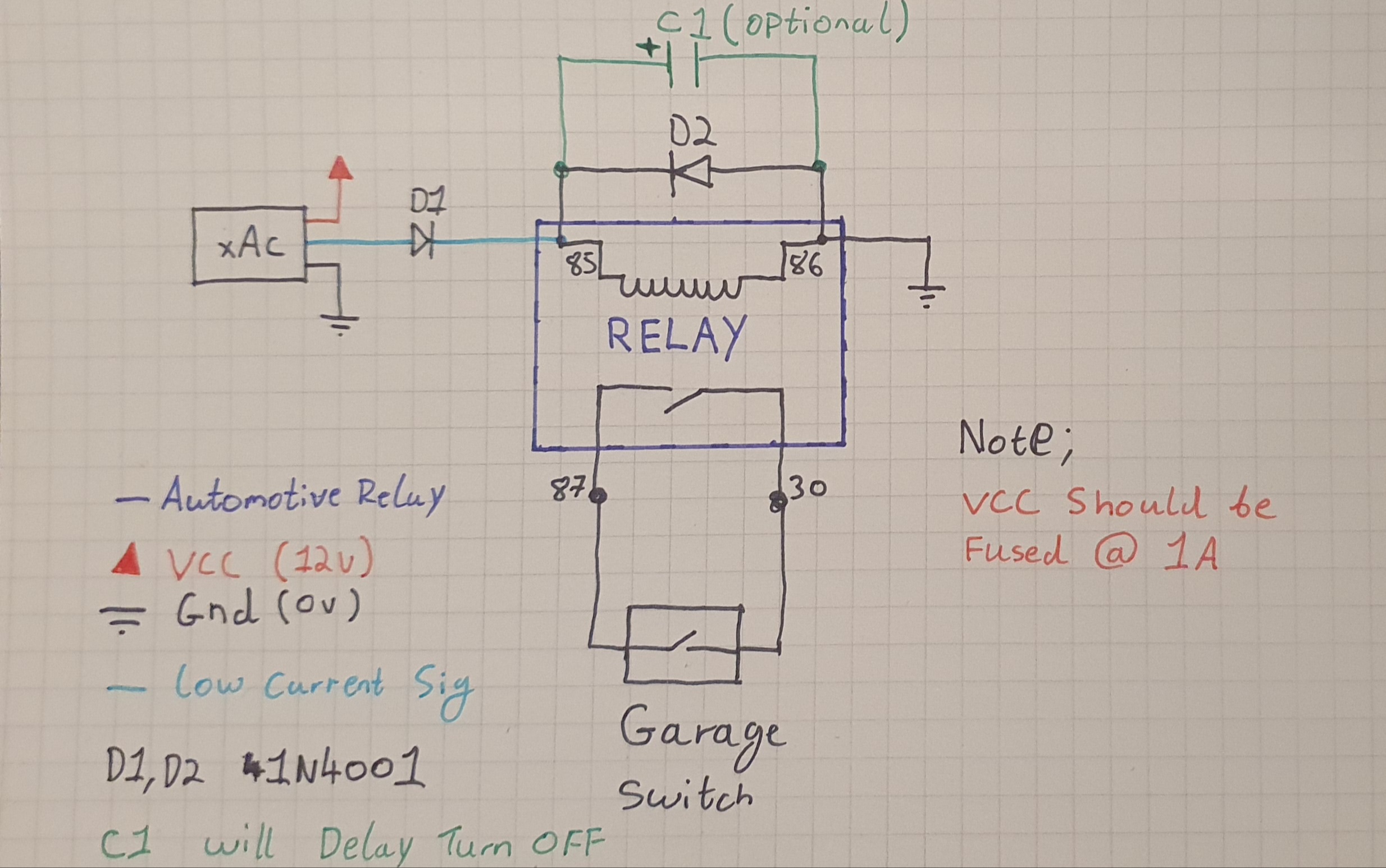
2 diodes, 1 protects the xAC the other helps suppress emf when the relay turns off.

I included the capacitor, this is optional. It will keep the relay on for a brief amount of time after the tag has scanned. (Needs to be big think 50uF+ 15v rated minimum)

As stated earlier only one relay is needed unless you need to drive a very large load.

EDIT: Looks like everyone wanted a go :sweat_smile:

6 Likes

Devilclarke, please forgive me for this, but I made a modification. For a non electrician itā€™s not intuitive what is, and what is not, inside the relay. Soā€¦ I put a purple box around everything that is INSIDE the relay.

Once again, please forgive me butchering your image, just trying to help out those who donā€™t read this the way an electrician would.

3 Likes

Yes, but I wasnā€™t putting a flyback in there.
Devilclarke did though. Basically I did D1 in Devilclarkeā€™s drawing, but not D2

1 Like

You might want to add the polarity marker. If itā€™s 50uF it will almost certainly be electrolytic, and if itā€™s put in the wrong orientation it will do nothing.

1 Like

Iā€™m anal like that so Iā€™ve updated my drawing and post, even used purple for you :wink:

It will go bang :wink:

1 Like

Whew!

I saw Satur9 replying, and I thought I was about to get whumped with the knowledge.

1 Like

You should still do this BTW.
Itā€™ll help you ā€œseeā€ it.

Donā€™t let us distract you!

2 Likes

Yeah my bad :flushed: @Steven1727 defiantly draw it down and keep it somewhere safe for reference in years to come when you look at it an go ā€œwhat the hell does that doā€.

Everyone happy now :stuck_out_tongue: all updated, purple relay for @ODaily and a + for @Satur9.

5 Likes

LMAO Yall crack me up!!! Thanks for the help and edits to my drawing @ODaily :rofl: I will try it out when I get home from work tomorrow morning and :crossed_fingers: it will workā€¦ if not I can go back to this :wink:

2 Likes

One quick note, @Devilclarkeā€™s point about the second relay making the trigger wire higher current may be needed in some applications, however rare.

The one-relay method is what I was getting at, I didnā€™t mean to have 2 in there. That said, if there has to be a particularly long distance between the xAC and the garage button, I could see the low current output of the xAC being an issue.

1 Like

The way the wires are ran the math ends up being about 48ft from the controller to the button

Yeah, Iā€™d leave the second relay there, that is a considerable run. Probably fine without it, but its not going to hurt you to leave it there.

2 Likes

Iā€™m curious now lol

1 Like

Didnā€™t know that. Probably why you needed two relays. If you really want to play with it, to get to one relay, then try using the relay closest to the xAC, and run the two wires from the button 48ft (using existing wire, of course).

Thatā€™s a long long way though.

Relay at 24ft? Divide the problem in half. Not practical, and still alot of wire to deal with.

Sounds like you might need to stay 2-relay.

Fun thing to try.

Step 1 Put one of your spare tags on the reader with tape to keep it on. . That way it will stay on while you test it. Now measure the voltage across the wires at the beginning of the 48ft run, and again at the end of the 48ft run. The wire will have some resistance, this will measure how much that resistance causes the voltage to drop.

Step 2 Put the signal wire back so that it runs through the 48ft wire using only the second relay. (which probably wonā€™t work). Leave your spare tags on the reader with tape to keep it on. Measure the voltage before and after the 48ft long run.

Sounds like the xAC canā€™t supply enough juice to keep the voltage up at the second relay. I bet step one has a slight, but acceptable voltage drop, but step 2 drops enough voltage that it canā€™t activate the relay.

Edit. Fun thing #2 Check the voltage before and after the diode. It should drop .7volts.

2 Likes

Willllll doooo :+1:. The wire runs up to my attic then along the beams where 2 walls are (roughly 22ft and 18ft ish), then down out of the attic lol. Lots of wire but makes it look super clean