what i am envisioning is essentially a cut down proxmark3 v2 no emulation or anything the whole analog front end design is basically there so should’t be massively hard.
I think the various modulation encodings and formats would still be an issue. The PM3 you issue a command telling it what you want to do.
I am not an expert in the electronics under the hood but only way I can naively see it working is if you basically run lf search repeatedly which would make it less responsive.
I am yet to see something like a lf hid watch that is ‘universal’
Unless it is universally configurable… that might work. So it wont work with any LF tag all the time but could be configured with a dip switch array or something in very vaigly same way the t5577 can emulate many cards but not at once…
I used to work for a large military supplier as a QA engineer. One of our products was an intervalometer for aircraft-borne rocket launchers.
The PCB for that thing was chock-full of shorts, connection bridges, extra resistors and caps tacked on as if they were aftertoughts - and the whole affair was then potted to avoid failure due to vibrations.
When I enquired about that sorry mess, and asked why we didn’t redesign the board entirely (which was my job after all), the reply was: as long as we modify the original board from the 60s, it’s a modification. If we redesign the board, it’s a new product and it’ll have to be certified by the FAA and the EASA as such - by modern certification standards. The 1960s board was never certified because it was a military product, and it was exempt back then, so we could do anything we wanted.
Yikes… The damn thing was more tacked-on modifications than original product. And I know for a fact that it’s still flying…
I saw some boards like that at my last job. I know they went into the rockets though not into the launchers. Anyway we had a specific path that a bunch of jumper wires had to follow and extra caps on the board then we had to tack down all the stuff so it didn’t move lol.
Hello, my first post, I call South Australia home.
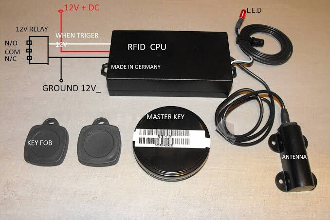
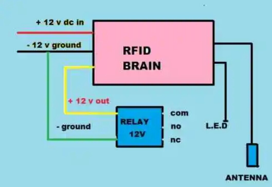
I would appreciate help wiring up a RFID reader.
I purchased a couple of RFID readers many years ago from a US serviceman.
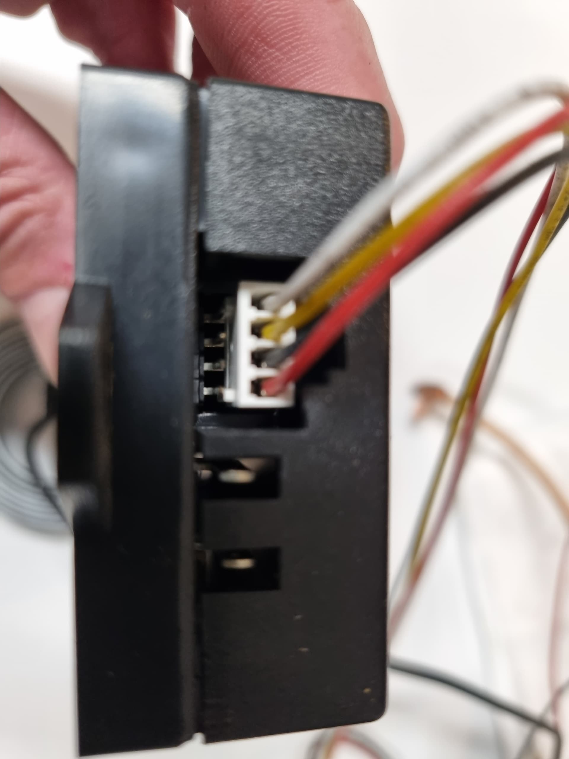
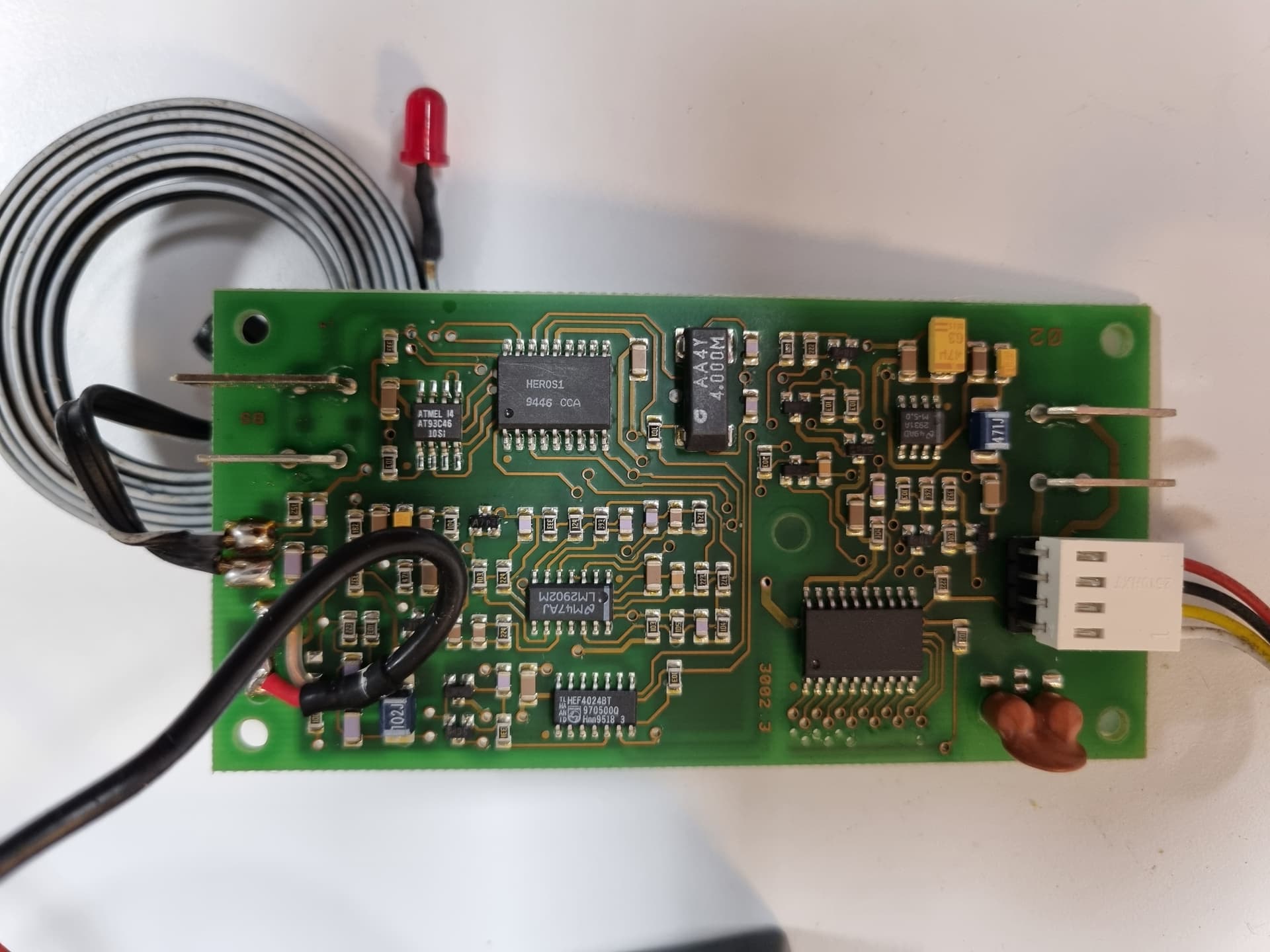
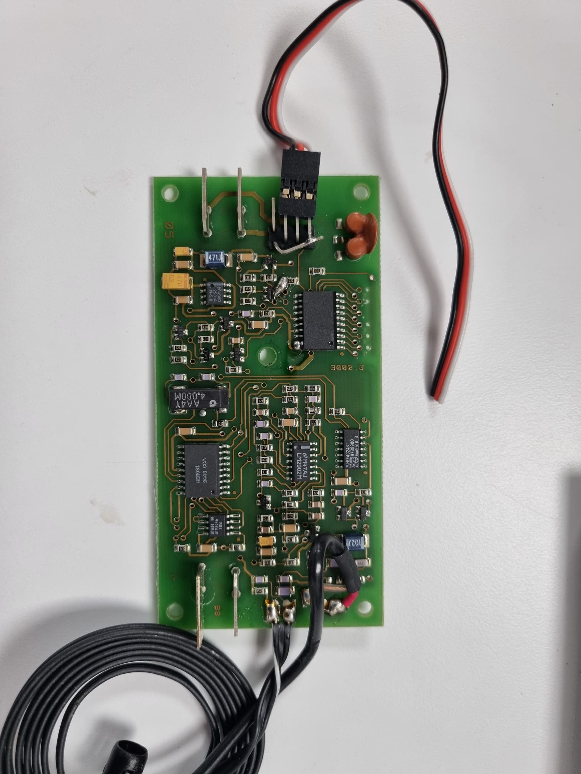
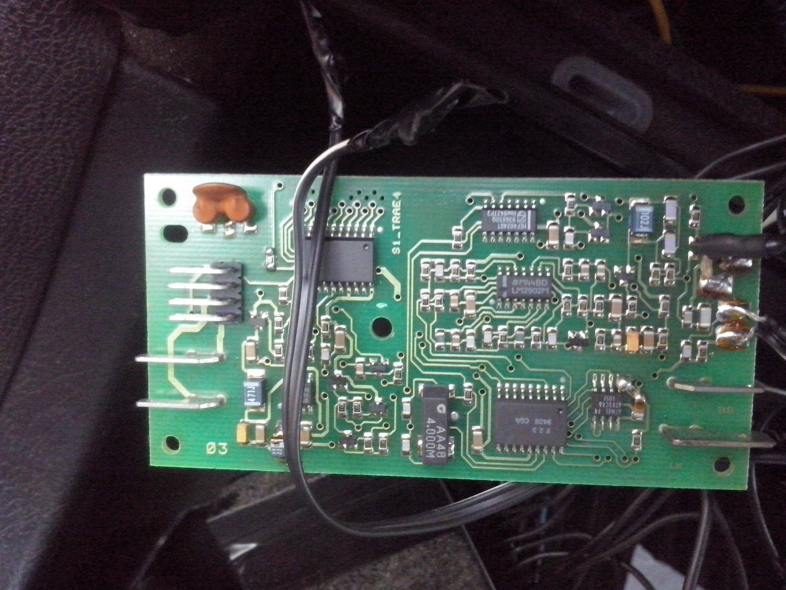
I think I have the original xEM Access Controller, but I don’t have the wiring connection information, and my readers didn’t come with the red/black/white or yellow wires, just the eight pin connector and the spade lug connectors.
I’ve tried tracing the eight pin connections back into the PCB and worked out the ground pin seems to be the second from the right top row, but that’s all that makes sense.
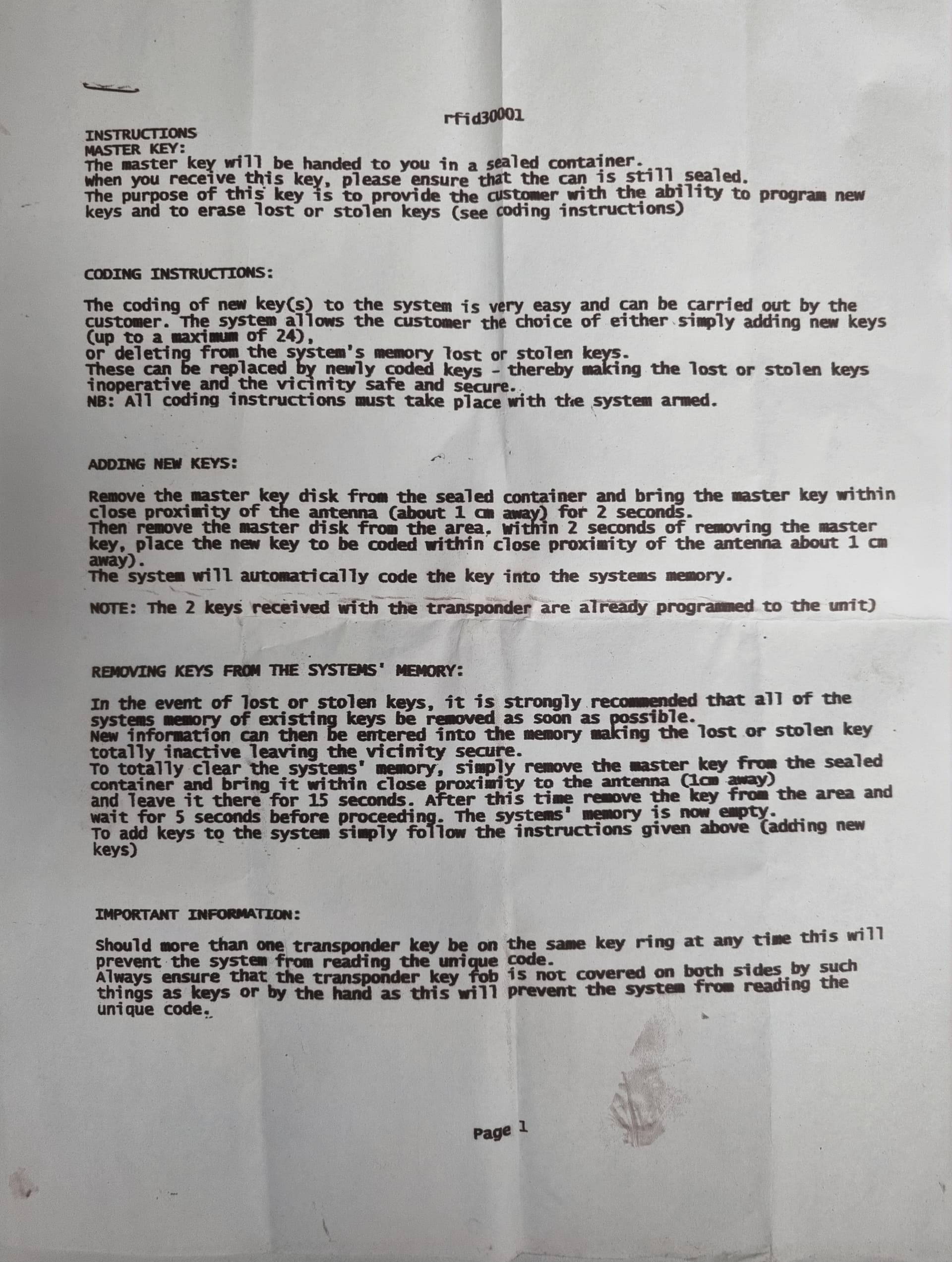
I haven’t done the mods as yet wanting a bit more clarification first, as I was told they both “worked”.
Mate, that’s a great, it looks like the wiring starts at the top row of pins positive on the right, then next pin going left is negative, then yellow and white being the outputs.
And the mods mention in this post haven’t been done – interesting!
I guess you know all about the tamper-proof screw!!! and how difficult it can be get it undone!!! You have technique!!! Lovely! Thank you


