Actually it’s the same as leaving it in the pin 2/3 configuration… I don’t think pin 3 is connected to anything, it’s just a holder for the jumper.
Ohhhhhh
4 Likes
One quick note on the video @amal - Trace isn’t always tip! If people are just grabbing a random supply of unknown origin from their PSU bin, it could very easily lead to the polarity being reversed.
Not sure how resilient these new boards are, but I’m a big advocate for team check-it-with-a-multimeter
4 Likes
seriously? i’ve never run into that… like ever… so i just assumed. wow… ok… learn something new every day!
They usually are but not always. The ones with the positive on the outside are usually devices that came with their own wall wart: throw the device away when it’s dead, keep the wall wart for when you need one. And then one day you grab it, check the voltage, and if you don’t check the polarity, there’s a fair chance you’ll be sorry.
I even have a couple that output AC in my parts box…
I have only ever seen a centre negative once, in an old Sony analogue video camera.
And THAT is the reason I test EVERY Time.

Right but this is not what we’re talking about… I am saying regardless of the polarity, the wire with the mark or trace on it always goes to the tip of the connector. That’s what we’re discussing. I’ve seen both positive and negative tip polarity, but the marked wire has always been the tip wire. Hence if the tip is positive, the marked wire is positive… and if the tip is negative, the marked wire is negative… at least that’s all I’ve ever seen.
That’s definitely the most common convention, usually a safe bet, but I’ve been burnt before!
I’ve also seen ones with the polarity marked wrong on the sticker (a whole pallet, we had to carefully label the whole batch and sell them off as clearance just to get them out of the warehouse!)
And for the whole centre-positive vs centre-negative. Most are centre negative, except for guitar pedals which are usually 9V DC Centre Negative. Except for the ones that aren’t…
All these things are great in theory, and I can usually figure it out from the wire with the trace, but QC is getting worse by the month and my meter hasn’t lied to me yet
1 Like
Ah yes okay. Well, It might be a convention that most manufacturers follow, but I wouldn’t rely on it. Also, I’ve bought stuff from China that was clearly wired by overworked children at the end of their 18 hour shift, and nothing surprises me from those factory - the mark used for negative least of all.
It takes 5 seconds to double-check with a tester (which I always do myself) vs. banging your head on the wall for an hour because your board is fried.
If you dont know why its interesting, the shell was used as positive in applications where there was a battery power option to. Using the shell means you can use the shunt capability of most dc jacks to connect a battery to the shell once jack us removed.
That was the original reason at least.
I watched a whole YouTube video on the subject, yes im that sad.
2 Likes
Oh, I’m well aware of the reason! The importance of what pole gets switched comes into play when you use a stereo input jack when you only use a mono signal, and let the mono plug short out ring and sleeve as an ‘on’ switch in addition to using the switched DC jack. The pedal shares a DC and signal common ground, so you need your battery/mains switching to be on the ground so you aren’t referencing your signal ground to VCC.
(I may have worked for a guitar amp and pedal design/manufacturer/repairer for a while - spent many days hand wiring boutique pedals)
2 Likes
Awsome, wasnt trying to tell you how to suck egg lol just thought it was worth the info being here and that was a cool insight thanks for that!
2 Likes
I know mate, I’m all up for the discussion and interesting tidbits being shared around!
2 Likes
true… unless… the meter has QC problems!!

4 Likes
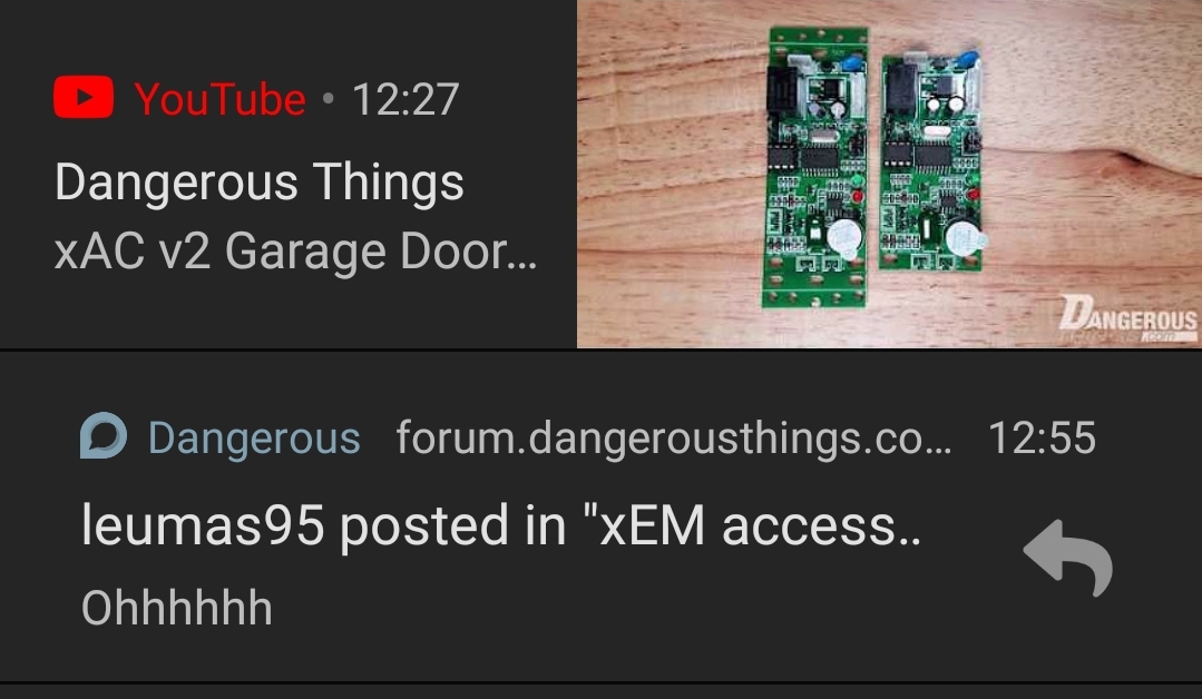
@amal Is there any way to order a replacement of v1? My bundled controller never worked properly come to find out. Or use the reader from v1 on a v2??? I FINALLY got around to ordering parts and wire up as a garage controller but for some reason i have 12.7v input but cant get the reader wire to output more than 7 volts resulting in the relay not being able to switch. The assembly screw was stripped out to so had to drill it out to even look at the board. Let me know.
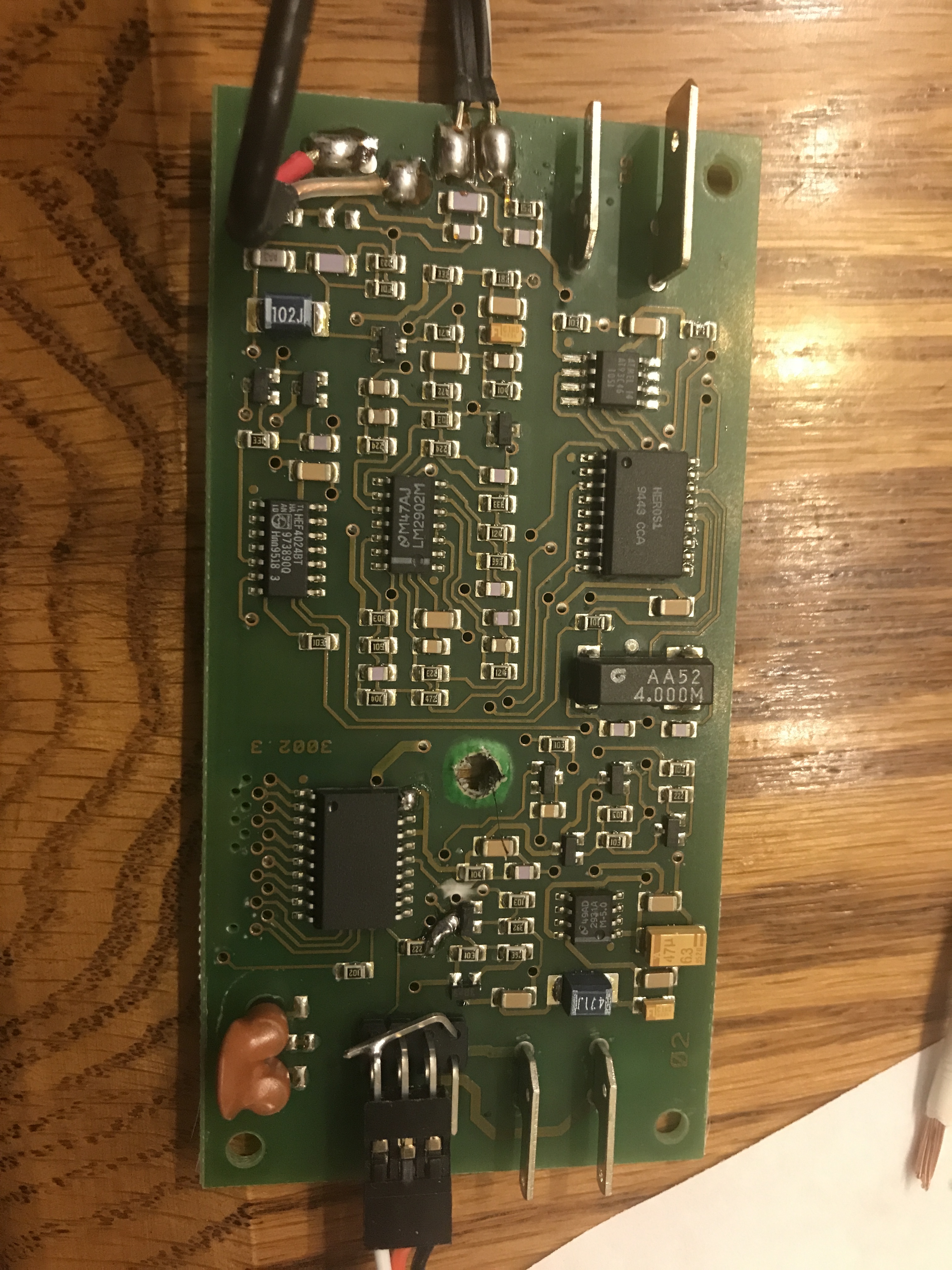
Actually this is a security screw… it’s not stripped, you just need the exact size flat blade to fit, or the security cross blade driver… but anyway we can replace your v1 with a v2… hit the orange help button thing on our website and send your order number and details… we’ll get you sorted.
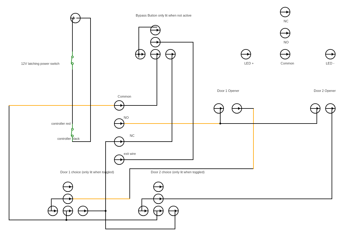
Well I figured I was so smart. Control 2 garage doors with one controller and even use a bypass to open/close from inside. Bought illuminated switches to help know which doors are currently toggled and to see where the bypass button was. Now im doing the diagram and dawned on me that with the built in relay its not going to output power so not sure how to have selectively illuminated buttons be powered. Ummm any ideas?[Buttons I ordered]https://www.amazon.com/dp/B083R69KS1/ref=cm_sw_r_cp_api_i_hNK-Eb7E8GJ4Z
Original
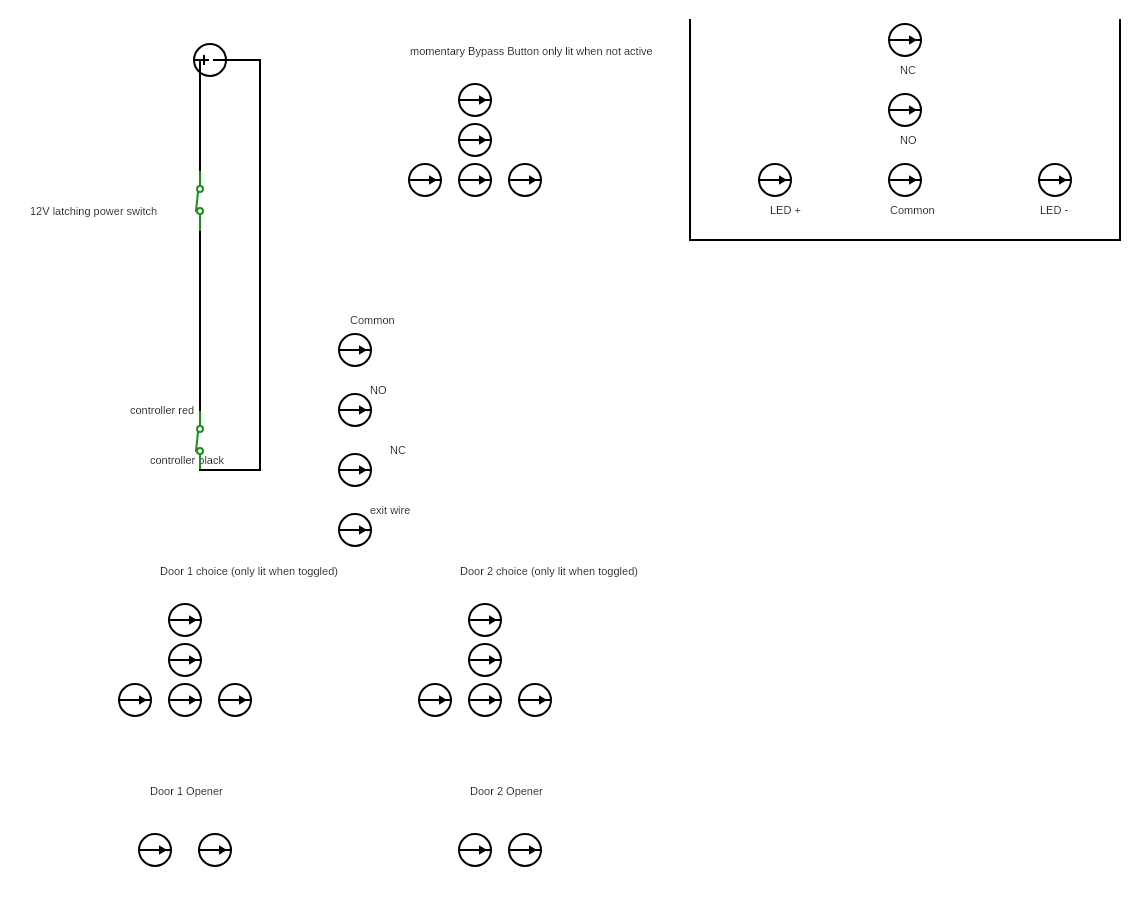
Template
Solution is very simple. Hook one side of relay to any kind of power you like (12v?) and the other side of the relay becomes an output of that voltage when triggered.
2 Likes
So would I then do a diode off the controller output common and merge that after with the power common? Then add relays between door switches and door opener circuit? So just need to add 1 diode and 2 relays. Any worry about current returning on the NC leg of the controller circuit?
Edit: dang I think I would need a relay on the bypass button circuit too right?