Sounds like something we can help you with.
Just copy and paste
Sounds like something we can help you with.
Just copy and paste

This is pretty much the same set up I have with my shuttle bus. Same wires and motor ect.
This is where Im lost.
How do I hook up the XEM controller v2 to activate the doors? Can it even be done? thanks again
Sorry for leaving you hanging buddy.
Yep
Now, what sort of support do you want?
Did you want to give it a go on paper and show us your workings? (no judgment here, just throw some squiggles on some paper and see how you go)
Do you want some prompts?
if so, read below:-
I thought I would start you off, I personally think you should give it a crack (On paper at least)
I’m not sure of you current level of knowledge, so excuse me if I am telling you to suck eggs ![]()
![]()
![]()
I watched the guys video last night before I went to bed. Considering he didn’t really know what he was doing and he got it to work! I thought he did really well,
I think, if you were to watch the Access controller video a few times, and the Bus guys video a few more times you will get pretty close to an answer.
A bonus little hint or two, the Blue wire will be your interior “Push to Exit” Wire, and you will want the output set on 5 secs

This one may also give you some clues

This one is a different controller ( The V1 ) but again, some good learnings in there

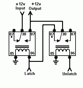
Something that I would consider, is a Flip-Flop Relay, “hard” to find but “easy” to make.
Something like this
Do you already have the access controller?
Do you have the ability to do a bench test?
Do you just want this handed to you?
We have some pretty clever people here, and an Electrical engineer like @Devilclarke for example, could probably knock out a wiring diagram pretty quickly for you.
Let us know, how you want to proceed
Apparently, I should also let some others contribute to give you a different perspective
What he said.
(I really don’t have anything to add, @Pilgrimsmaster has done a great job of breaking the outline down and unless you want a wiring diagram handed to you I don’t see anything massively missing).
Thanks for the detailed reply, I greatly appreciate it!
To start, the wires in my bus door motor are slightly different in color. In the video, he has red (always has power), yellow (gets power when you open the door), white (power when you tell the doors to close), and black that is ground wire. For my wire diagram setup, I have both red and black but in place of yellow and white I have orange and purple.
On the Banvie door system, we determined that there were 6 wires from the wire loom that we needed to use- two whites (solid white and a white wire with a black stripe), two yellow wires(that get spliced to the red wire), black and red wire.
From the video, I determined that the solid white wire went to the white wire in the door motor, purple wire in my set up. The white with black stripe went to the yellow wire in the door motor, orange wire in my set up.
From there, I ran the black to the negative terminal on my battery and I spliced the two yellow wires to the red wire and ran that to the positive terminal on the battery.
When pressing the open or close on the key fob, you can hear it clicking but nothing opens or closes. I’ve set the Banvie opener to 5s. I’ve also tried flipping the wires but still nothing.
I just received the access controller last week and unfortunately don’t have a way to do a bench test.