To be fair, they’re not associated. It’s just in the same thematic realm. I also really like Electric Wizard
3 Likes
Still trying to calculate.
Numbers for air core are too huge to deal with.
Decided to try ferrite core, see if it would push it into a workable range.
Using THIS 2mm x 15mm Ferrite rod core.
and this https://www.allaboutcircuits.com/tools/coil-inductance-calculator/
I came up with a best case of:
548 turns
.08274" loop dia. (2mm + .004inches for wire dia)
.004" wire dia.
31 relative permeability
= .0382H or 38.2mH
Unfortunately, that gives a coil length (548turns * .004") of 2.192"
The core is only 15mm, or about .590" long.
To get it on the rod, I’d need at least 4 layers, but the online calculator doesn’t do that and I can’t find a better one. In the absence of a better idea, I’ll set the loop dia to the middle of the layers of the coil.
So…
The center of the coil is at .09474" dia. (OD is effectively .11074" and will fit in a 2.8128mm id tube, call it 3mm)
500 turns (125 per layer x 4)
.004" dia wire
31 permeability
Gives 0.0380H or 38.0mH
Coil length of (125 turns per layer *.004 wire dia.) .500" long.
Distinctly weird when you start getting round numbers like that, but there it is.
Thoughts?
Yeah, inductors with a core material are too complicated to simulate. You need to know everything about the core. The only way to do it is to use $10k software like COMSOL.
You’re just going to have to roughly estimate, wind more than you need, measure with the meter, remove some, measure, repeat… Until you get the correct value. 4 layers of 125 turns on a 15mm diameter ferrite rod with a 12.7mm length sounds reasonable. Luckily 38mH is well above the tolerance of the budget LCR meters. Most of them only go down to 2uH, so winding coils for HF applications can be a challenge.
Don’t lose heart. The inductor for the LF xLED is only slightly less Henry’s than what you’re trying to wind. Preparing to do the work is hard, but it’s actually pretty easy to tune it once you know what’s up. It’s going to feel so good when that LED lights
And… I just gave digikey more money.
LEDs
magnet wire (assorted)
1206 package 220uf capacitors
ferrite cores.
Ought to be enough.
You know, if this does work, then that last tube is the only option.That’s pretty frackin big.
1 Like
Tried again. Failed again. I now know one more way that doesn’t work.
I got my ferrite cores in.
Things I learned:
Ferrite Core #1. I was winding it by hand (literally), but handling it that much caused the wire lead for the first turn to snap off, just as I was almost done. Bummer.
Ferrite Core #2. Turns out they’re kinda brittle. Smashed it by accident.
Ferrite Core #3 Wound this one on the drill. But, I have to wind almost the whole thing, and there’s nothing left to hold onto. So I super glued it to the head of a nail, then broke it off when done. Worked good for winding.
I still believe I’m off on inductance. Not gonna get any further until the LCR meter shows up and I can make some “to spec” coils.
Also. I need one of those giant magnifying glasses on an articulating arm / stand.
3 Likes
In a PM you asked if you would be better served by a raw iron or soft ferrite core. Wanted to share my answer here for others.
I’d use ferrite. There’s three factors affecting your choice: permeability, coercivity, availability
Magnetic permeability is the mu variable you often see in formulas relating to coils. More permeability means a stronger field will be induced within the implant. Ferrite generally has a larger permeability than raw iron (unless the iron was annealed in the presence of an external field).
Coercivity communicates how difficult it is for an external field to realign the magnetic domains within a material. For a permanent magnet, you would want high coercivity (hard to change). For the core material in a transformer which has to alternate frequently, you would want low coercivity (easy to change). Since the coil in implants is essentially one side of a transformer (the other being the transmitting device) you definitely want a low coercivity material. Raw iron has a slightly lower coercivity than soft ferrite, but they’re both miniscule and 55Hz is an extremely low frequency for this type of consideration, so it shouldn’t matter.
Ferrite is a ceramic material constructed from rust and trace other metals like nickel, cobalt, and aluminum. It’s extremely abundant and cheap. It is usually not electrically conductive or chemically reactive.
Raw iron on the other hand can be more difficult to come by. It’s very reactive with oxygen, so it usually comes in the form of mild steel which has a few percentage points of carbon in it’s makeup. Steel is very different magnetically. Both iron and steel are also electrically conductive.
5 Likes
Thanks!
I got… some… of that. I’ll keep working on it.
This project is pushing my brain around corners I didn’t know existed. Fun, a little confusing, but fun.
5 Likes
LCR meter showed up today, and I wanted to see how far “off spec” my last coil was. So I cut it back out and checked it.
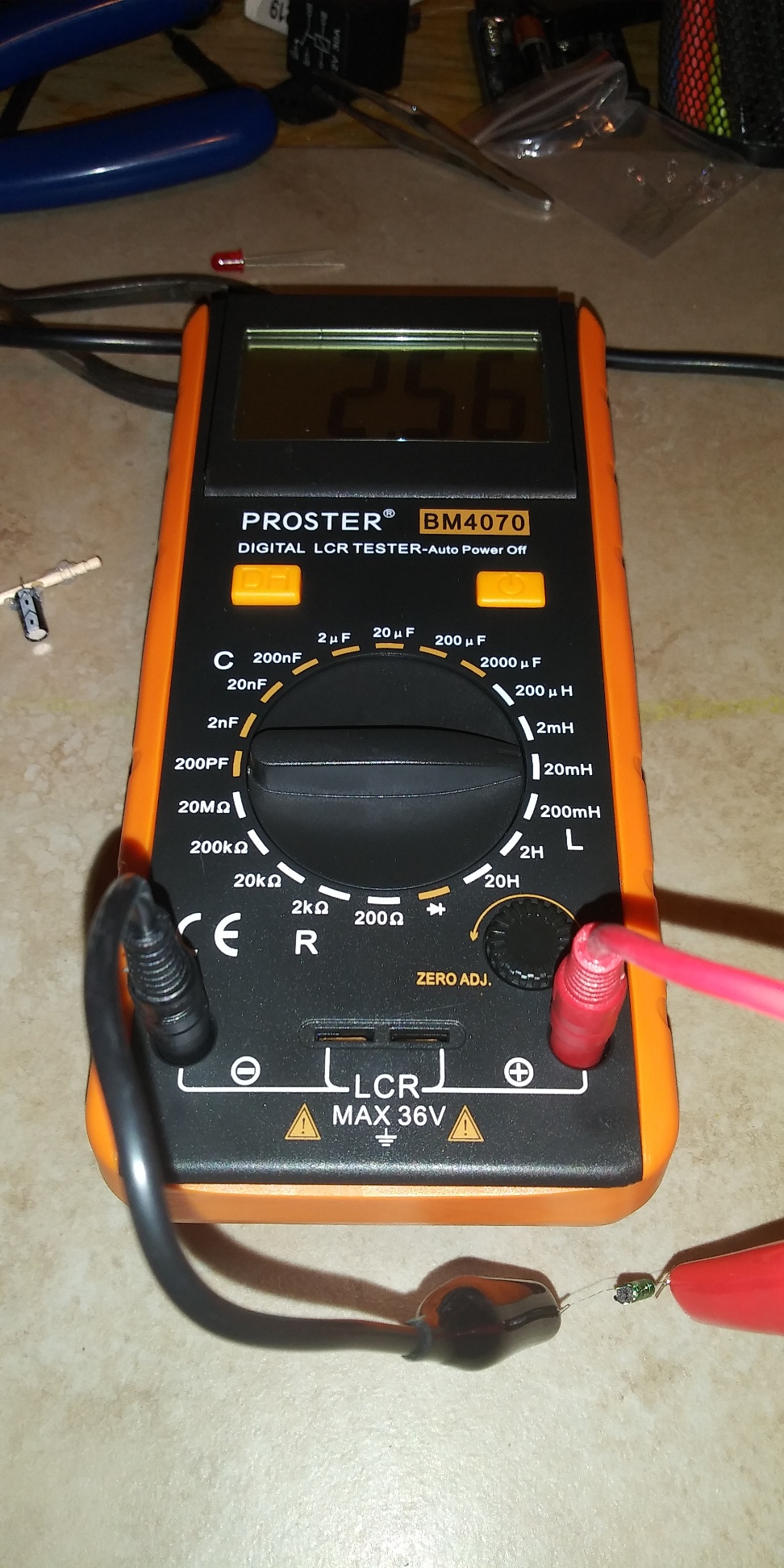
2.56 mH I was expecting something close-ish to 38.0
Not sure what the misfire was. Gotta work tomorrow, probably won’t get time to work on it till Sunday. I imagine it’s for the best. The more I think about it, the more likely I can figure where I went wrong.
FWIW, The coil was wound as close as I could get it from one end to the other, in four layers. This is as good of an approximation of the calculated numbers above as I could get.
2 Likes
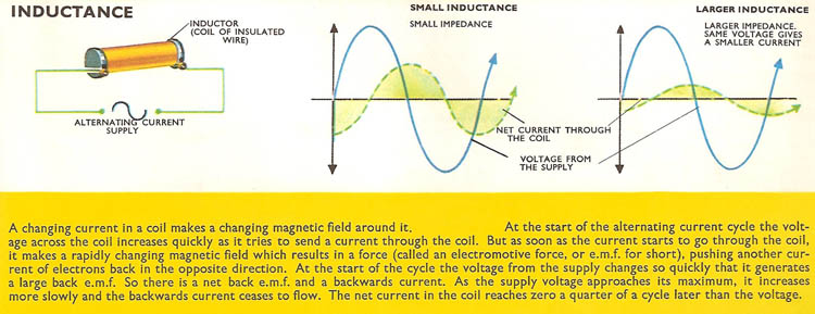
Just a heads up. Inductance is the resistance to changes in current flow caused by the relationship between electricity and magnetism. It is not frequency dependant, it’s a static value for each coil.
Impedance is frequency dependant. Impedance can really throw people through a loop, but it’s actually not that complicated. It’s just regular resistance, with some added or subtracted based on capacitance, Inductance and frequency because we’re using AC circuits.
Think of the circuit as a water pipe and inductors like springs.
When you open the valve to push water through a pipe with a spring in it, the spring is going to push back. If you had a stopwatch, you would be able to tell that it took longer than expected for the water to flow out the other side of the pipe. This is just like how inductors cause current (flow) to lag behind voltage (opening the valve).
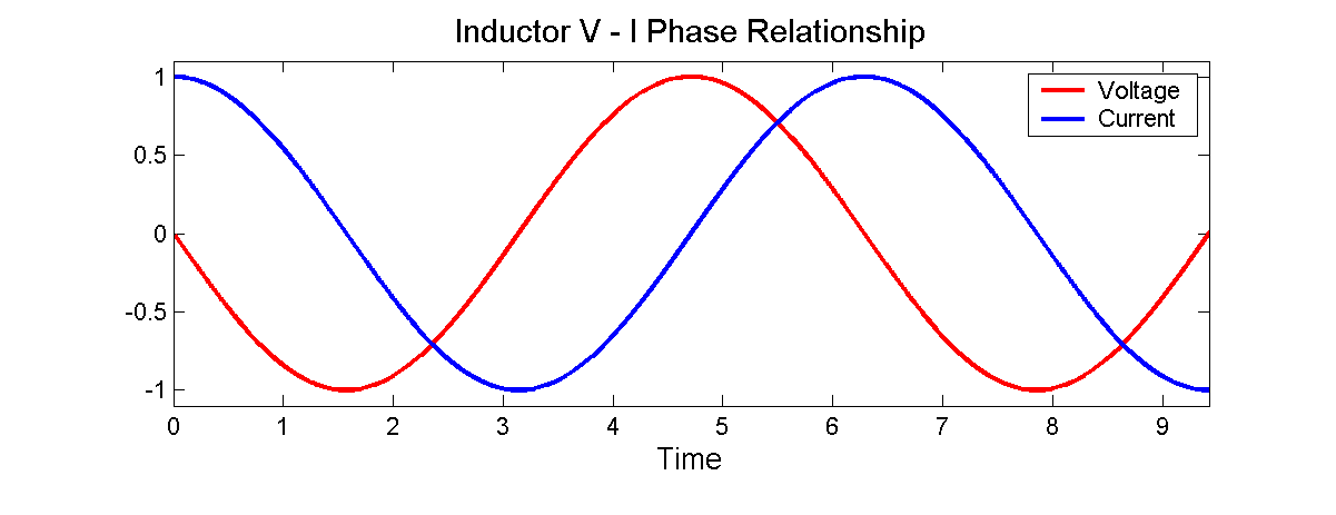
Inductors are slow to change, so they react well to low frequencies and poorly to high frequencies. The bigger the inductor or the higher the frequency, the more that red line (current) will lag behind (shift to the right) that blue line (voltage).
In addition to the lag, inductors can also add to the resistance, which reduces the magnitude of the current.
Alright, I take that back. It is super fucking complicated. Science, yo
3 Likes
This, this is 100% true I was completely confusing inductance with impedance!
Thanks @Satur9 for setting me straight and bruising my ego ![]() haha no hard feelings though.
haha no hard feelings though.
There’s a really good (simple) explanation of the difference between resistance, reactance, and inductance here
I’m going to delete my comment as to prevent confusion but suffice to say I made a mistake. I apologise.
3 Likes
You’re good, no need to apologise. You weren’t intentionally spreading misinformation. It’s not like anyone who’s not immersed in this stuff cares about the distinction. It was mostly an excuse to drop some knowledge.
3 Likes
Ain’t that the truth ![]()
2 Likes
But but… this is very confusing: water springs out of pipes, but springs out of springs also - especially in the spring! Also, hope springs eternal but water doesn’t - it’s a pipe dream.
So how does that translates into equations?
2 Likes
Glad I’m not the only one.

So I need a plan…
At this point, theoretical calculations are not matching measured reality.
I’m gonna assume my reality is, well… Real. My theory must need some work.
Step one, gonna go back and re-assess my values used in calculations. Hopefully I made an error and I can correct it.
Step two. I think I should make a simpler coil, say 75 turns on a single layer, and see if the calculations match up to the measurements. This could be a result of my exceeding the limits of what the online calculator is capable of.
Step three. If nothing else, maybe I can divine a correction factor. If I’m always off by X percent, then just divide my intended inductance by that figure and calculate using that as a target.
Step four. Ditch theory. Just wind a shitload of coils and see if I can iterate my way into something useable.
2 Likes
Yep thats about right haha, not helpful I know but not much that can be said.
Have you tried this calculator I’ve used this for work stuff and always appears to be pretty good. It needs alot of variables poped in but really is very good.
2 Likes
I might have found it.
The calculator asks for Relative Permiability.
I used the spec for Effective Permiability.
Unfortuneatly, I know not what these are, or how to calculate one from the other.
That site looks good. Gonna hafta dig a little more before I can use it though. Too many gaps in my knowledge to fill out all the fields in the calculator.
1 Like
I’ve never had any success with the calculators that work with any core material. I usually wind an air core coil and then try the same dimensions around ferrite to figure out some kind of permeability correction factor like you suggested, then recalculate.
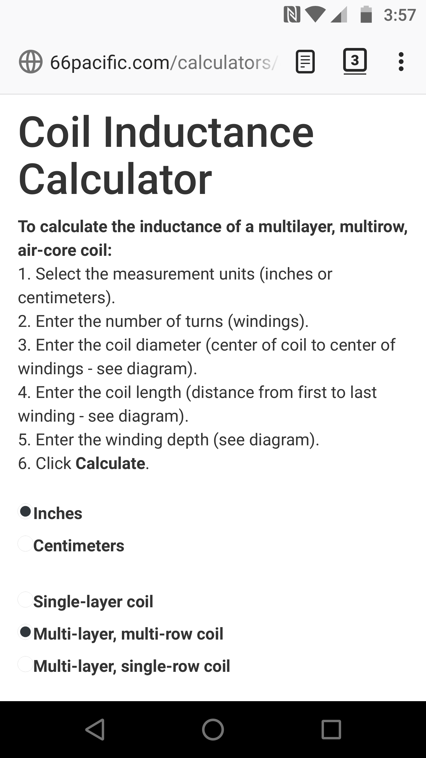
Here’s a step by step of calculating the Inductance of an air-core coil using this calculator (it will work for any of them). Unfortunately you need to do a few calculations yourself before you can plug values into the calculator.
For this run we’re going to make a coil 1 inch (shudder) long with 28AWG wire wrapped around a 0.0787" diameter toothpick in 3 layers. Make sure your calculator is configured like below
You can figure out the diameter of the wire your using on this page. 28AWG wire is 0.0126" in diameter. To figure out how many turns it’s going to be, it helps to think of the coil’s cross-section.
You can divide the length of the coil (1") by the diameter of the wire (0.0126") to get the number of turns per layer (~80). If you multiply that by the number of layers (3) you get the total number of turns (240).
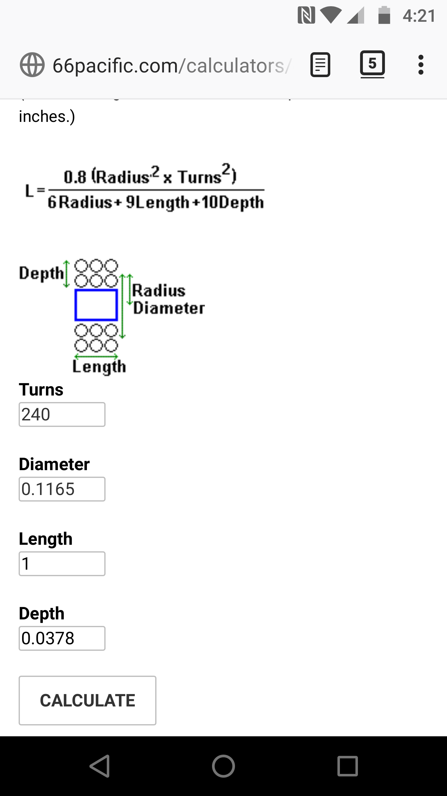
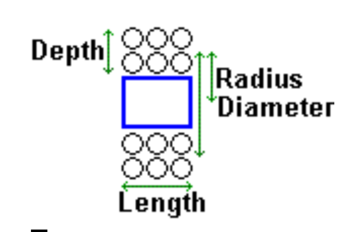
Now the only values we’re missing are Depth and Diameter. Depth is just the diameter of the wire times the number of layers, so 0.0378" in this case.
Diameter is the tricky one. The diameter of the entire coil is not the total width. It’s actually the distance from the centerpoint of the windings on one side to the centerpoint of the windings on the other side. This is because the equations going on in the background require the average diameter of the windings, which is an imaginary ring in the middle of the copper wires. This is compared to the Depth to determine the core diameter. It’s all very confusing, but that’s how it’s calculated.

After you plug all that in you can hit Calculate to get the Inductance at the bottom. As you can see it’s going to be miniscule compared to what you need.
I’d start by winding a much larger coil and prove the concept of a 55Hz xLED before you go breaking your neck trying to make it tiny.
1 Like
I gotta give my brain a break for a bit on this.
So I went looking for capacitors. (I know, not much of a break, sheesh!) Guessing that the largest diameter tube might be necessary (3.19mm). What do you think of a 470uf cap to bring the inductance value down? THIS might fit in the tube. Max size with tolerance included is 2mm x 1.6mm (stood on end) which should fit in a 2.56mm diameter circle.
If, (big IF) I’m calculating right, then that drops my inductance to ~17.8mH. Possibly a much more acheivable value / size.
BTW, thanks for sticking with me while I mush this out. It REALLY is appreciated.
2 Likes
More Inductance and less capacitance is going to work much better for this because of the whole impedance thing Devilclarke and I mentioned earlier.
Capacitance it’s fast and Inductance is slow. Since you’re intending to use this at 55Hz (a very low frequency) you’re going to want as low a capacitance as possible. That’s why I keep suggesting you start large and work your way down. The coil in the LF xLED has almost as much Inductance as the one you’re trying to wind now, so I know it can be done in the smaller form factor
4 Likes
Necro alert.
I haven’t given up on this yet, but the latest test tells me I’m gonna hafta go another direction.
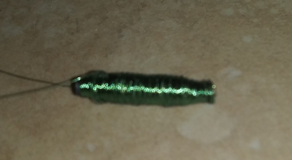
Specifically, I tried the old, “just wind the wee out of it” method. No way or attempt to count the windings, I just went as fast as the drill and my fingers could co-operate. The coil I ended up with was a 2mm ferrite core, same as before, with a diameter of 3.8mm (as big as the outside diameter of the biggest glass tube, and an inductance of 9.86mH. By the time I get it up to 38mH, it’s gonna be as wide as it is long. I just don’t see any way to make the coil in a viable size.
I do wonder about a flat coil.
For reference, a fat little bugger.