Hey guys, I’m looking to put together a new lock/unlock circuit on a new car. Same deal as my last project, wiring directly into a key fob circuit board with a relay and lock/unlock the car that way.
Last time I looked into this, the only solution I had was to get two xEM readers, wire one for unlock and one for lock. What I would like to do this time is use one reader to perform both functions with a latching flip-flop relay. Based on the (very little) knowledge I have about latching relays, they will hold their position closed until they receive another pulse from the reader to switch positions, like constantly holding the unlock/lock button on your key fob.
I’d like to know if anyone knows if there’s a relay that will switch to a position, then release, then switch to a different position on another pulse, then release, as if it was only pressing the button instead of holding it? I’m driving myself mad trying to find something like that or come up with some convoluted may of making it work with different relay boards.
Any chance you could use something like an Arduino to handle the inputs and control two separate relays? Then you only need one reader
I think you could also diy a circuit that does what you’re saying, briefly activates two relays one at a time, one per button press and switches them off automatically (at least, I think that’s what I’m understanding)
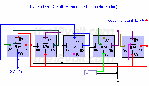
With three relays and an SR gate if you don’t want a fancy controller board like an Arduino involved.
So, assuming you only care about authorized users unlocking the car, you could use a normally open button (or reed switch, hall effect proximity switch etc if you are magnetically inclined) to trigger the locking function. No latching necessary as all the locks need is a pulse to actuate. Buuuut you could also just use the car’s existing l lock switch. Or attach a timer relay’s coil or switch terminal to the unlock wire while the common is attached to the car’s lock terminal/wire so it would automatically lock after a certain amount of time.
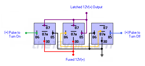
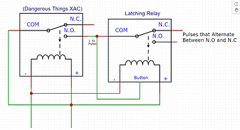
Latching is generally accomplished (in my world) with a three wire start/stop setup. This requires a relay and both a normally open and closed control (button or some such). Power flows through a normally closed (stop) button then to a NO terminal on a relay (common attached to the relay’s coil) while a normally open button is powered from the “far” side (opposite where the power enters) of the stop button to the relay’s coil as well. When the relay closes, the NO terminal feeds the coil. When the normally closed button is pressed it opens the circuit to the NO terminal, killing the power to the coil which opens the relay. Hopefully this made sense.
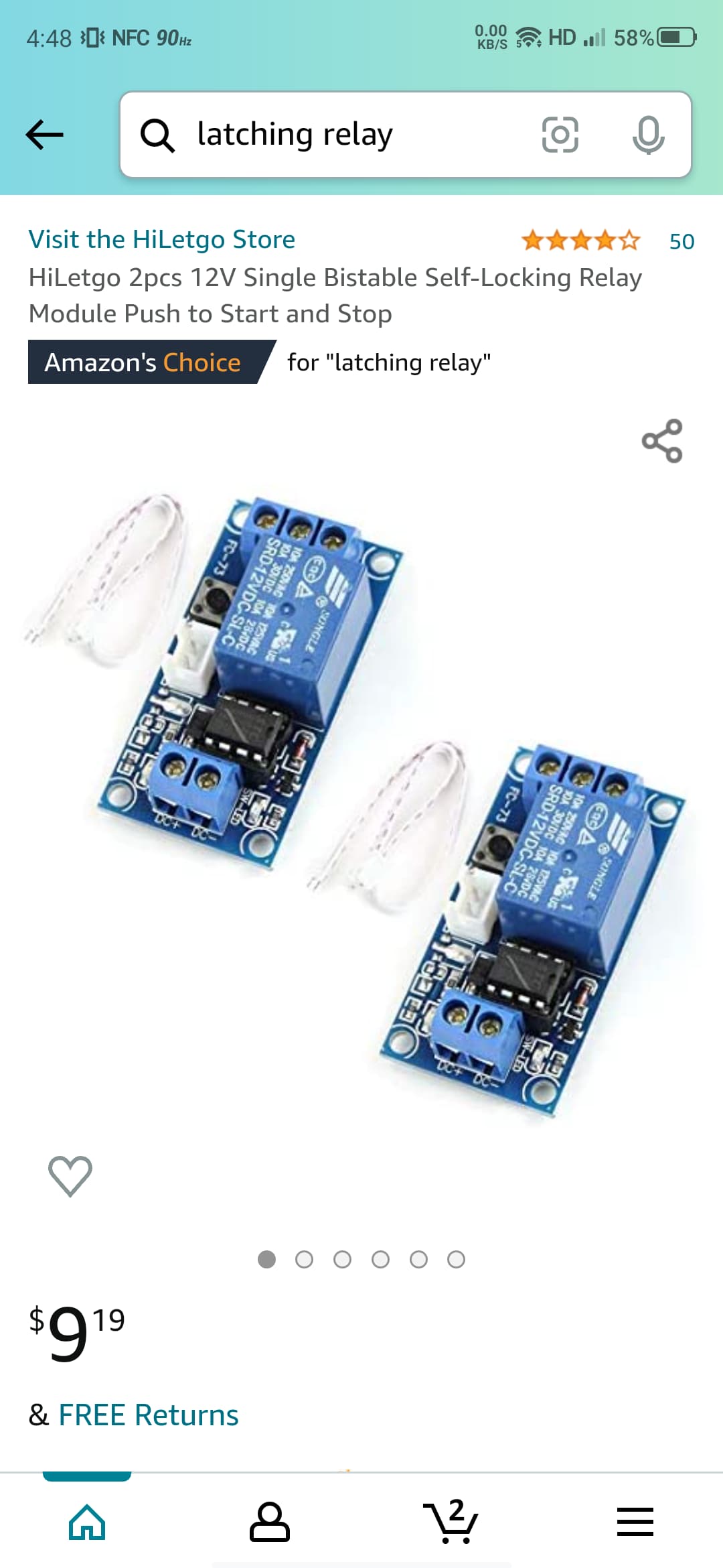
I have been looking at grabbing one of these for testing
“Latching relay that will remain in its open or closed state when power is removed, i.e. it will remain on or off and not automatically return to off. A negative (-) voltage pulse is required on either terminal 1 or 2 to switch on or off.”
One of the things I like about the12V.com is how there will be all the variations of each layout. ie. if the is a +ve trigger circuit, there will also be a -ve trigger circuit, so you don’t even have to interpolate, just follow the diagram
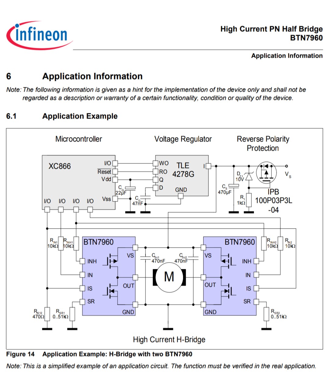
I have been using the BTS7960 module coupled with an Arduino+PN532 reader to lock and unlock my car. The BTS7960 module is a high current H-Bridge motor driver that can turn a pulse of 3.3v into a pulse of 12v that can be directly connected to the door lock actuators. Being an H-Bridge the BTS7960 can also send the same pulse with reverse polarity to actuate the locks back to their original position.
Here is a link to where you could buy one:
Here is a wiring schematic from the BTN7960 datasheet. This schematic shows two BTN7960 in the same H-Bridge configuration as the product from the Amazon link.
I admit the BTS7960 does not solve the problem of creating a pulse. I use an Arduino for that, this allowed me to tune the length of the pulse so that the actuators don’t burn out.
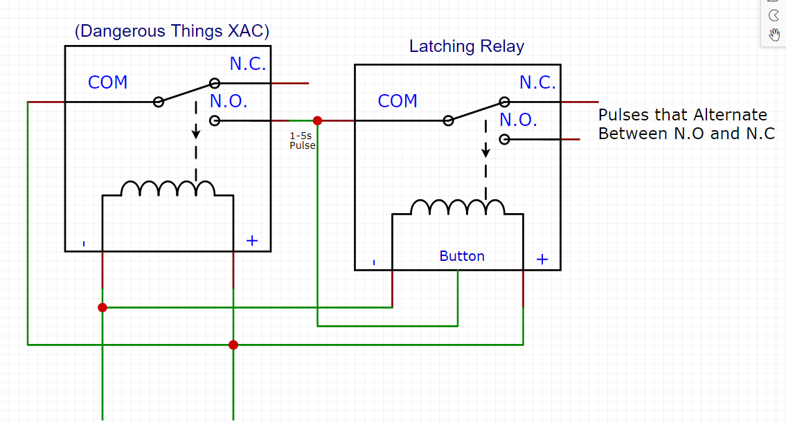
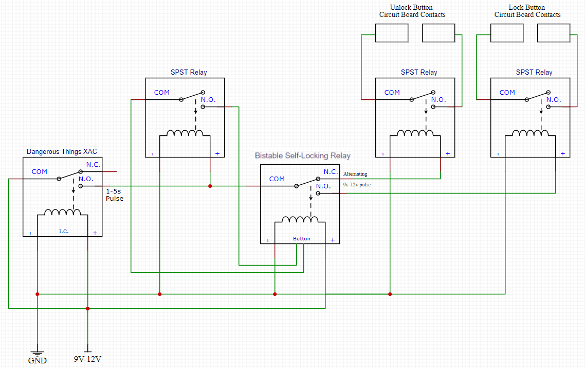
Yea one problem I should mention is the 9v-12v that the XAC v2 requires should not be used directly on a key fob. I believe OP is attempting to use relays to bridge the fob’s circuit board contacts, so I suggest the alternating pulse control two additional SPST relays that act as the fobs buttons.
Another problem I’ve noticed with the schematic revolves around the “button”/trigger of the latching relay. The latching relay’s trigger voltage needs to accept the XAC’s 9v-12v otherwise, magic smoke… If the latching relay has a button then the button would need to be replaced by an additional SPST relay. The whole schematic only works as long as everything is 9v-12v.
I appreciate that! Just trying to help in a timely manner
I think this would require the latching relay that @Pilgrimsmaster mentioned earlier which can maintain state without power. I just thought it
was worth mentioning that this is not a feature of all latching relays. Possibly something for OP to plan towards because a latching relay that can maintain state would save battery life.
Hi all, I’ve made some progress with my circuit design, thank you all for your input!
I have something in the works involving the xEM Access V2, two switch relays and a flip-flop latching relay. Just trying to solve the issue where the trigger for the switch relay is a 12v high signal instead of a closed circuit. Sure something is out there but if I’ve found it I don’t know it yet lol.
Really appreciate all the suggestions here, watch this space! Order on it’s way with a NExT and a Spark 2.
Most “latching” relays I come across do not maintain their state after power is lost. These latching relays use a small flip flop circuit (usually activated by a button) connected to a standard relay coil. This means if the power is cut, this latching relay will default to the Normally Closed circuit, not remaining latched. I use this type of “latching” relay in the schematic above. (Edit: They are called Bistable Self-Locking relays) Also, the SPST Relays used in the schematic do not have a trigger in other words they need to actuate the instant 9v-12v is applied to them.
I feel like this video should accompany my schematic because I am not an electrical engineer.
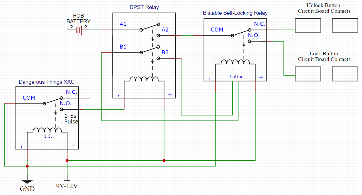
I believe there is a way of removing one of the relays if you can determine whether the key fob’s buttons pulled the contacts on the circuit board high or low. Here is the schematic for that. Though I should mention this method should only be used by professionals as connecting the battery directly to the button contacts could be harmful to the key fob.
You have given me exactly what I’m looking for! Once the pieces arrive I will assemble this circuit and test it. If it works as intended I will be extremely grateful. Thank you so much
I apologize @Eriequiet for the confusion, I was completely wrong. Amazon’s choice for a “latching relay” has led me to incorrectly refer to a “bistable self-locking” relay, as a “latching” relay. OP needs a bistable self-locking relay for all of the wiring diagrams above. I think I can set up a small demonstration of different relays to help myself aswell as any other future passerby. Please let me know if I’m misinformed.
Relays come in all shapes and sizes, all of the following relays function the same way: When their electromagnet is powered, a switch is actuated which closes (or opens) a circuit. The switch will remain in that state until power is removed from the electromagnet.
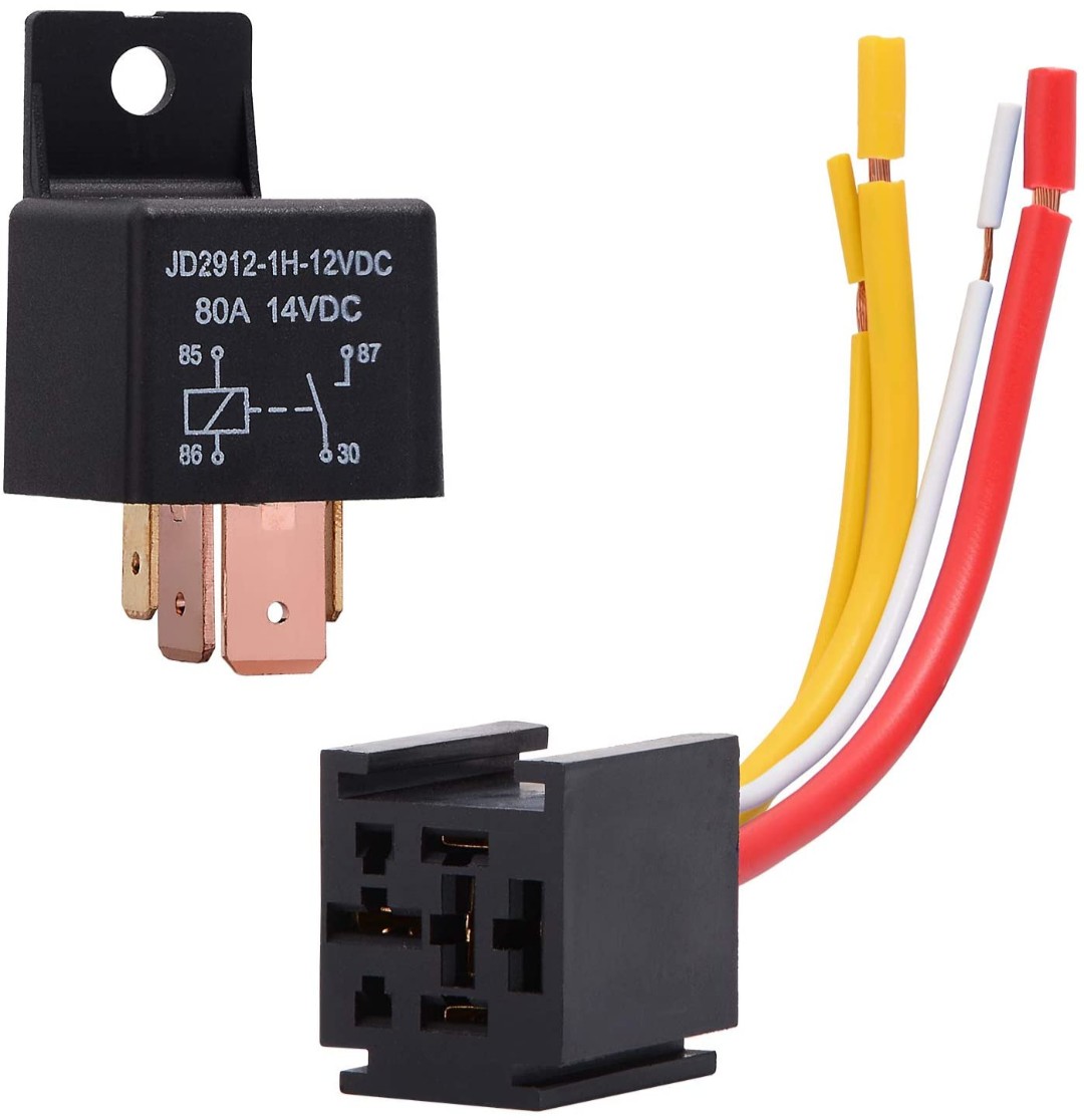
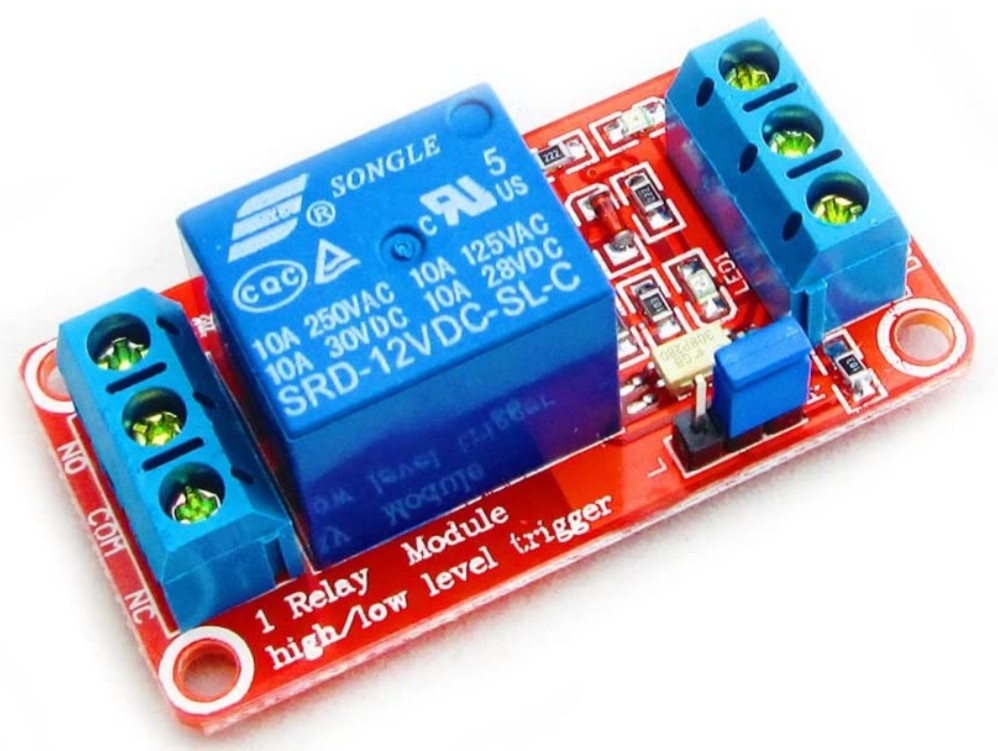
This SPST relay is one of the types used by Electroboom in the videos above. Since these types of relays are rated for high current, they are usually sold for automotive purposes.
This is an example of a standard SPDT relay mounted on a pcb, this type is connected to power at all times which allows for activation by a high/low level trigger. The SPDT relay can be thought of as a SPST Relay with the addition of a Normally Closed (N.C.) terminal for signal inversion.
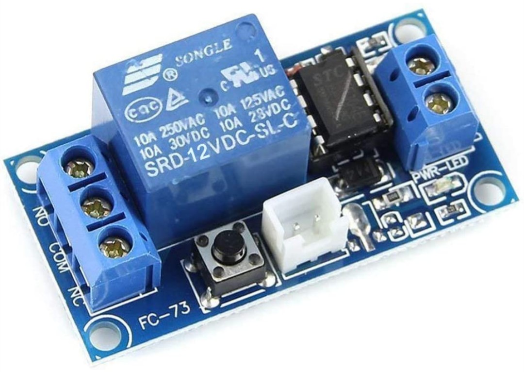
This relay is what I incorrectly refered to earlier as a “latching” relay. It is actually called a “Bistable Self-Locking” relay which operates using a D Flip Flop Circuit not a physical latch. This means it will not hold its state when power is lost.
Tip: Inside the prominent blue boxes of each pcb relay is where the electromagnet and switch are housed. Since the bistable self-locking relays are manufactured with the same electromagnets and switches as the standard relays, it can be easily determined that neither will be able to hold their state without power.
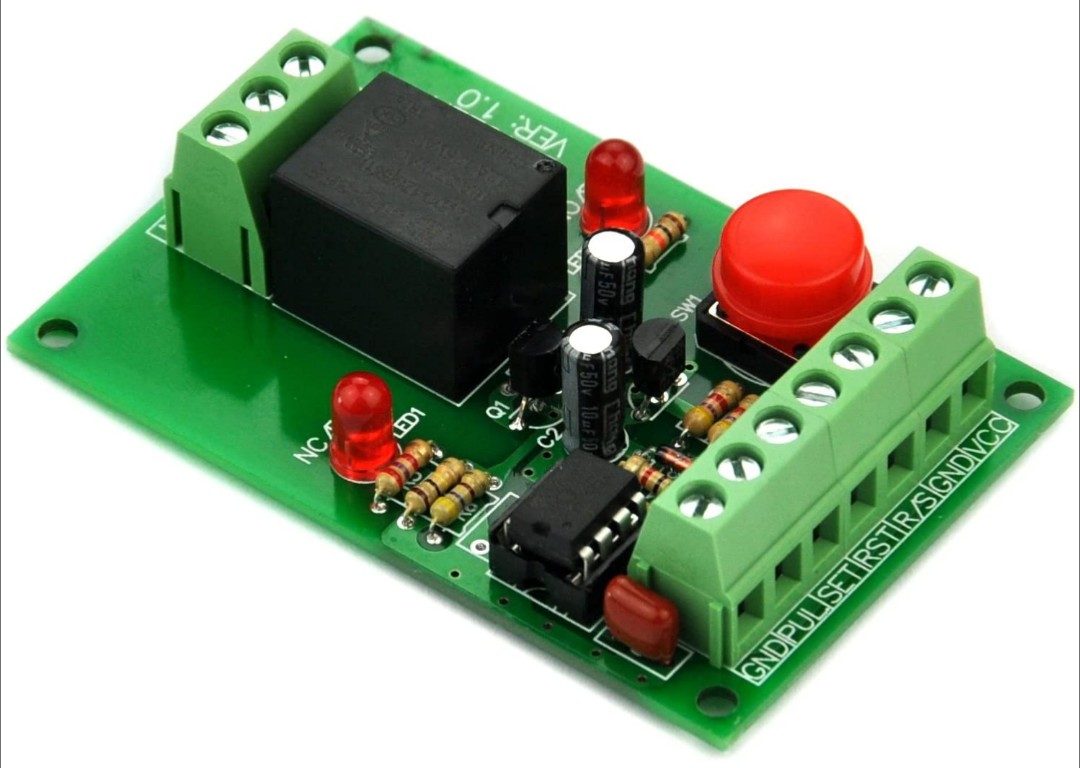
Although the prominent box of this relay is a different color than the other two pcb relays, AFAIK it is the same standard electromagnet and switch configuration. What makes this relay interesting is that it has a dual Set/Reset trigger. This means it has the potential to work for both Eriequiet’s suggestion and the diagrams I drew up. The seller claims that the relay will revert to its last held state when power is reinstated. That might cause technical difficulties though if current can flow through the relay before the switch is able to revert. The effect would be a “glitch” similar to the edge detector featured in the “D Flip Flop Circuit” link above.
Edit: Changed fragile links into pictures and some other stuff. I’d also like to share this post I just found: Wiring Diagram Repository.
Just a quick progress update, I’ve started putting the circuit together, but I’m still waiting on the XAC reader to arrive. Latest shipping update said next Monday to Wednesday.
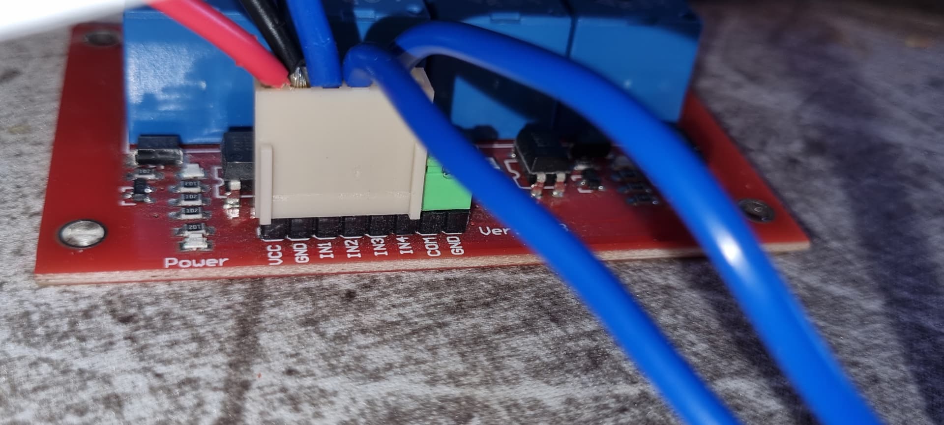
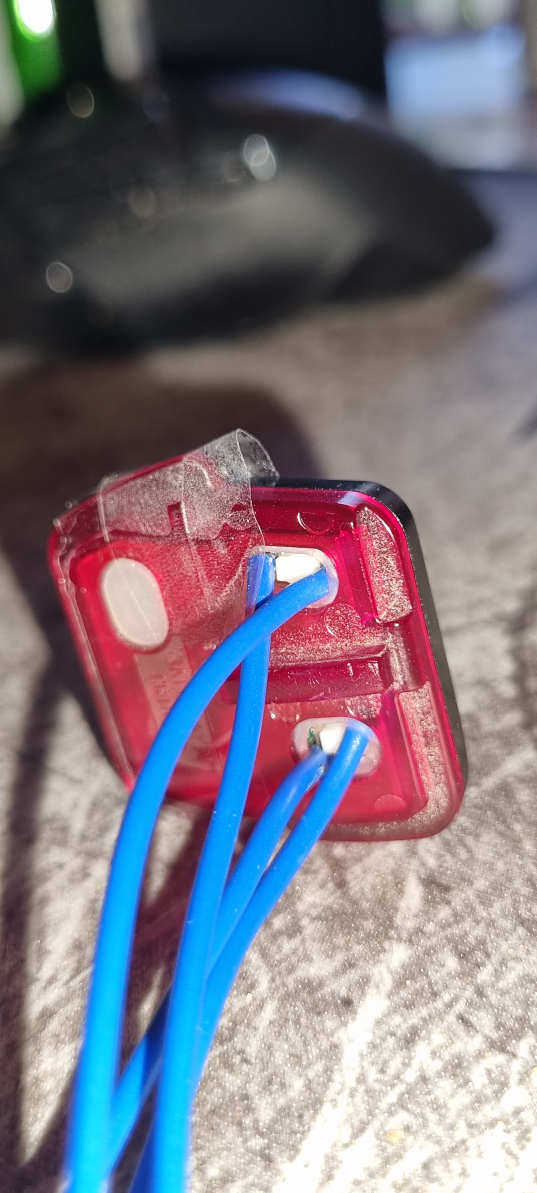
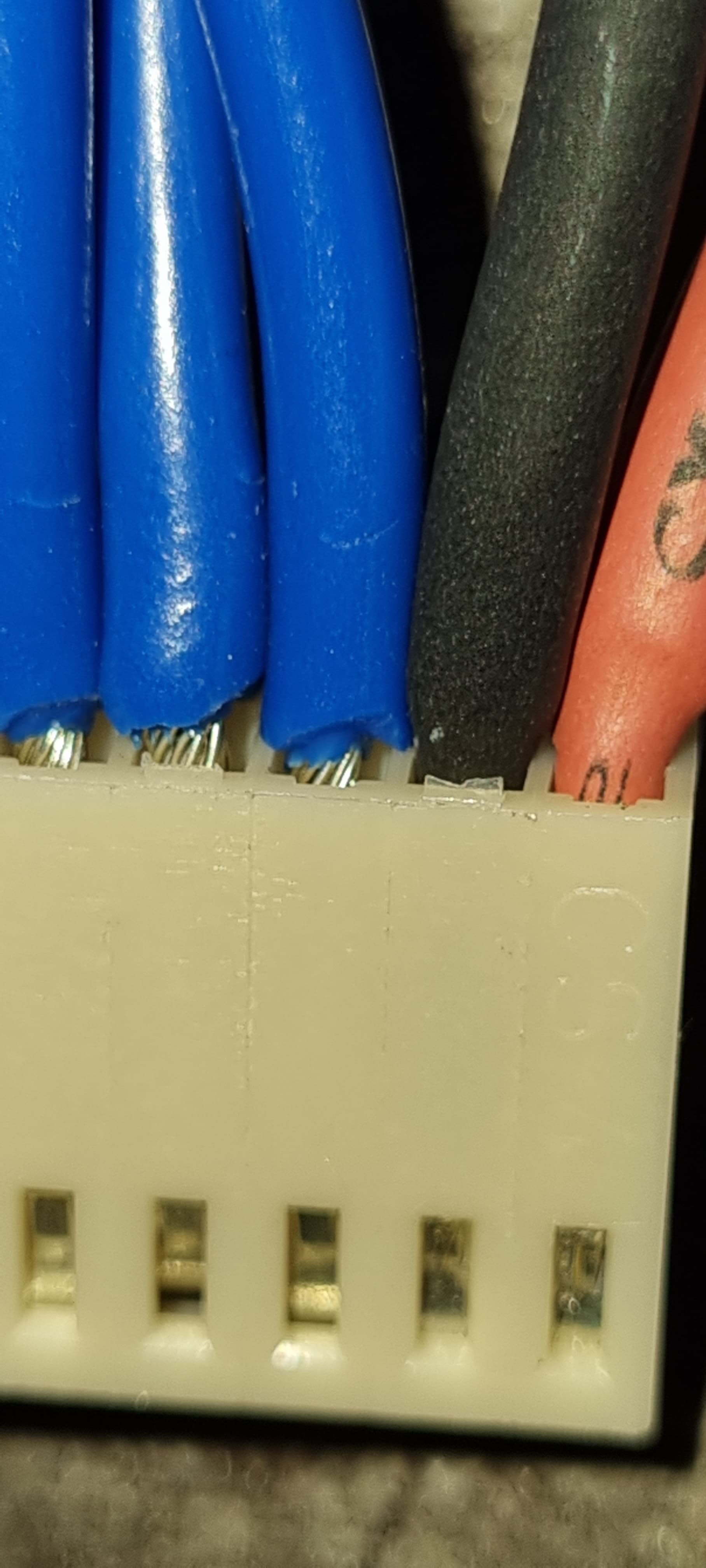
I got my hands on a bistable latching relay from China and paired it with a 4 channel relay board I had laying around from my previous project. I have wired it up based on the diagram provided by @AbbottSmith, minus some of the COM connections.
The key fob was very easy to disassemble, and with a slight modification to the membrane I was able to run the wires directly from inside out to the relays. The internal switches were a bit tricky to solder to as I only have one sized iron tip, but with patience and constant testing to make sure I didn’t break it, I have a working connection between the lock and unlock buttons. I’m considering potting the inside of the key with epoxy to relieve some stress on the solder joints, but I’m not sure yet.
I will post another update once the XAC arrives. In the meantime I need to think about a mounting position in the car and running a 12V bus to the area.
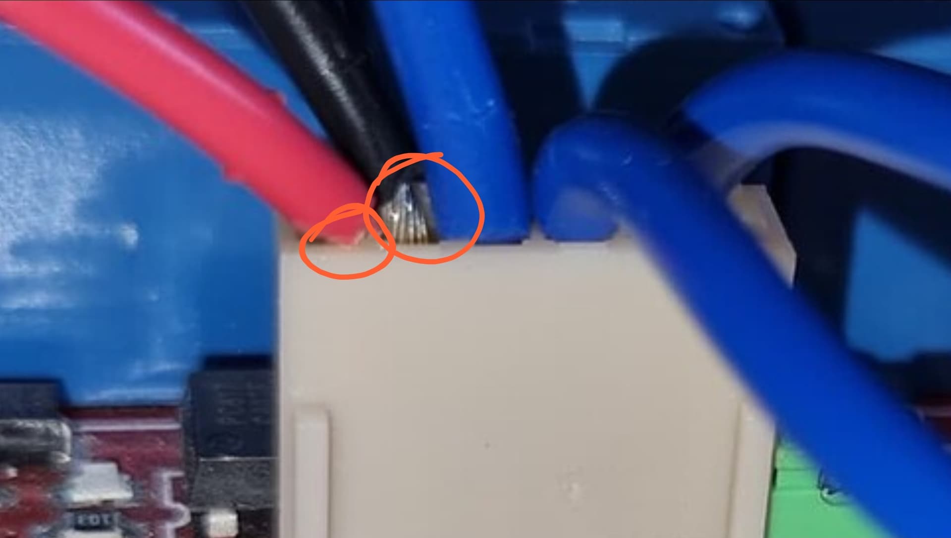
Thank you for pointing that out @Pilgrimsmaster. I have now resolved this issue. I will also be running a 10A fuse inline to ensure I don’t blow anything up


