I apologize @Eriequiet for the confusion, I was completely wrong. Amazon’s choice for a “latching relay” has led me to incorrectly refer to a “bistable self-locking” relay, as a “latching” relay. OP needs a bistable self-locking relay for all of the wiring diagrams above. I think I can set up a small demonstration of different relays to help myself aswell as any other future passerby. Please let me know if I’m misinformed.
Relays come in all shapes and sizes, all of the following relays function the same way: When their electromagnet is powered, a switch is actuated which closes (or opens) a circuit. The switch will remain in that state until power is removed from the electromagnet.
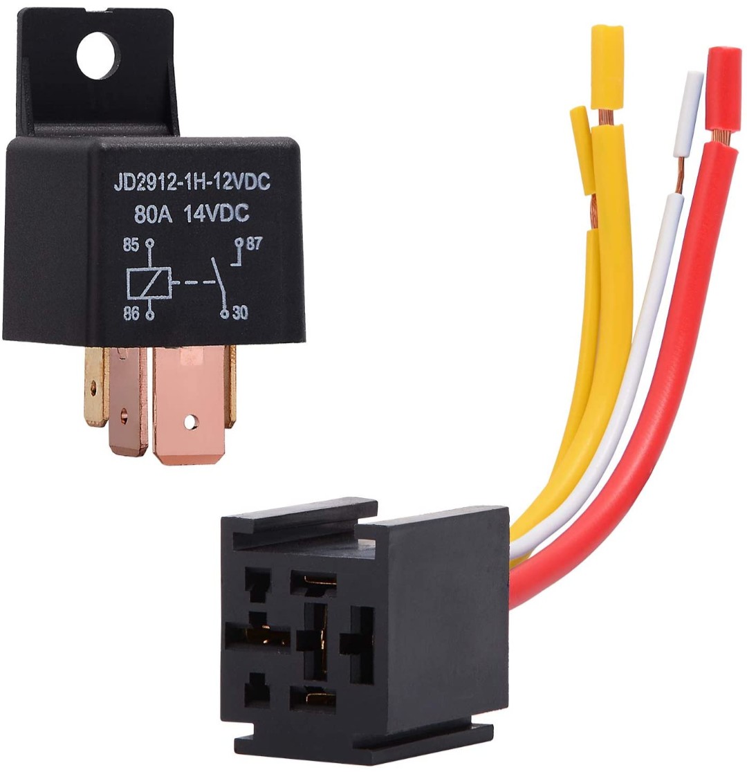
This SPST relay is one of the types used by Electroboom in the videos above. Since these types of relays are rated for high current, they are usually sold for automotive purposes.
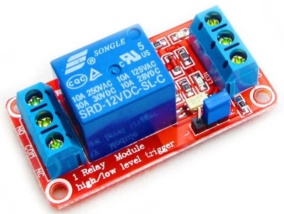
This is an example of a standard SPDT relay mounted on a pcb, this type is connected to power at all times which allows for activation by a high/low level trigger. The SPDT relay can be thought of as a SPST Relay with the addition of a Normally Closed (N.C.) terminal for signal inversion.
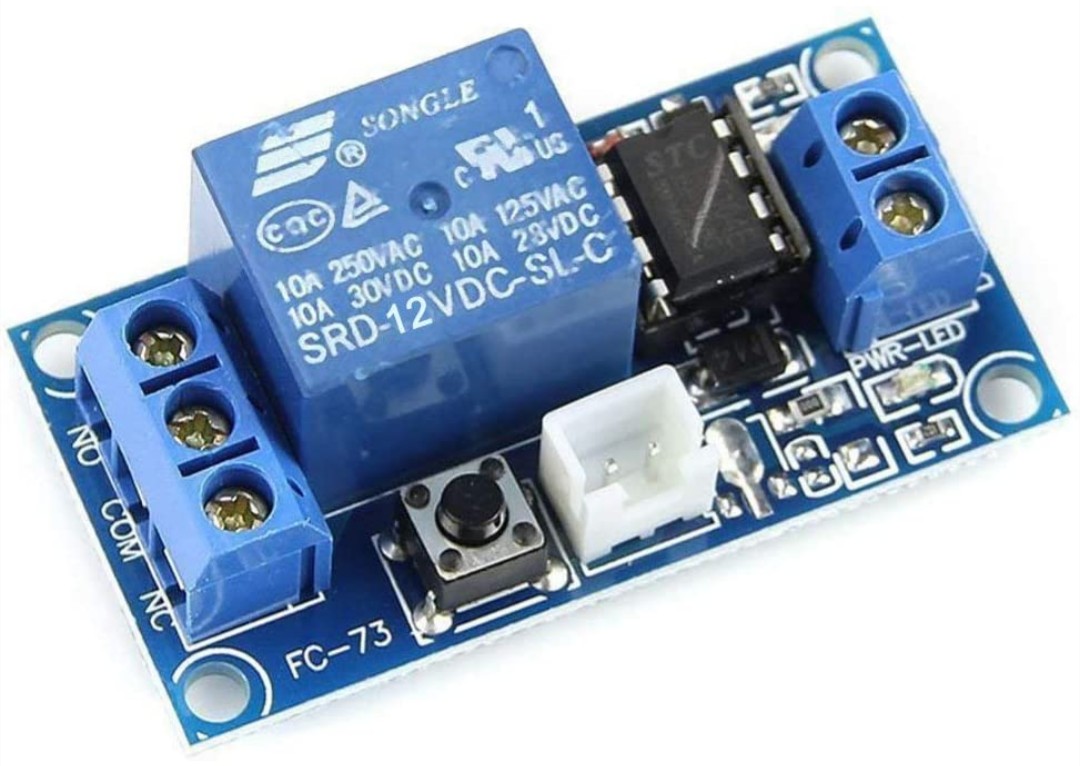
This relay is what I incorrectly refered to earlier as a “latching” relay. It is actually called a “Bistable Self-Locking” relay which operates using a D Flip Flop Circuit not a physical latch. This means it will not hold its state when power is lost.
Tip: Inside the prominent blue boxes of each pcb relay is where the electromagnet and switch are housed. Since the bistable self-locking relays are manufactured with the same electromagnets and switches as the standard relays, it can be easily determined that neither will be able to hold their state without power.
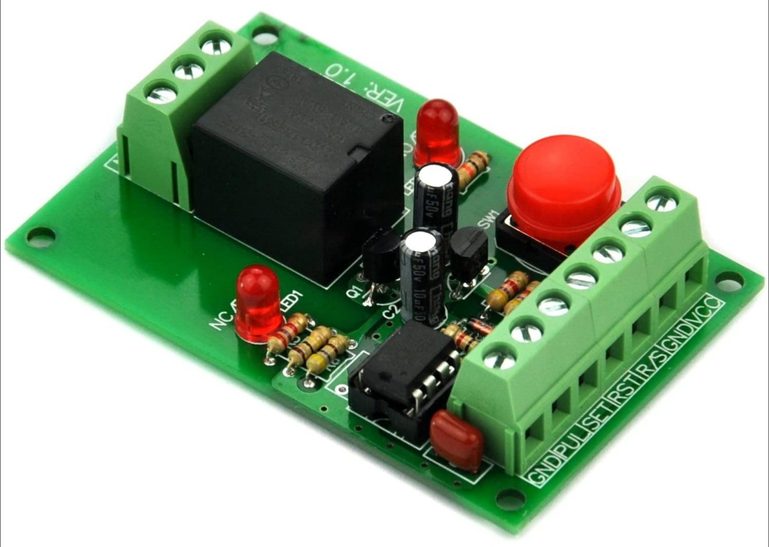
Although the prominent box of this relay is a different color than the other two pcb relays, AFAIK it is the same standard electromagnet and switch configuration. What makes this relay interesting is that it has a dual Set/Reset trigger. This means it has the potential to work for both Eriequiet’s suggestion and the diagrams I drew up. The seller claims that the relay will revert to its last held state when power is reinstated. That might cause technical difficulties though if current can flow through the relay before the switch is able to revert. The effect would be a “glitch” similar to the edge detector featured in the “D Flip Flop Circuit” link above.
Edit: Changed fragile links into pictures and some other stuff. I’d also like to share this post I just found: Wiring Diagram Repository.