Custom Ignition Switch Replacement with xEM

So I was bored this afternoon while I was watching some TV and I saw the post “CaRFID Custom Ignition Switch Replacement (Open Source)” (sorry I dont know how to link the post) and I was thinking that there must be a way to do what the OP of that post was doing with the xEM. But I am a noob, but when I was younger I installed remote start systems in vehicle and alarms for a living so i know a little about these things, but I have never designed a system like this. I decided to take a shot at and and see what you guys though about it, so far I have gotten nothing but wonderful help on this forum. Below is my first attempt at designing anything in a CAD program so please go easy on me.

I would love to hear all of the ways that I messed this up so I could make it better, or if it is not needed at all, I just wanted to spend some time doing something and learning something that I have never done before, Thank You again!

3 Likes

(OP of CaRFID here)
First thing is, I assume by xEM on the diagram you mean the xAC. Also, this reply might come off a bit negative, but know that I’m just giving feedback, and I wish you and your project the best :blush::+1:

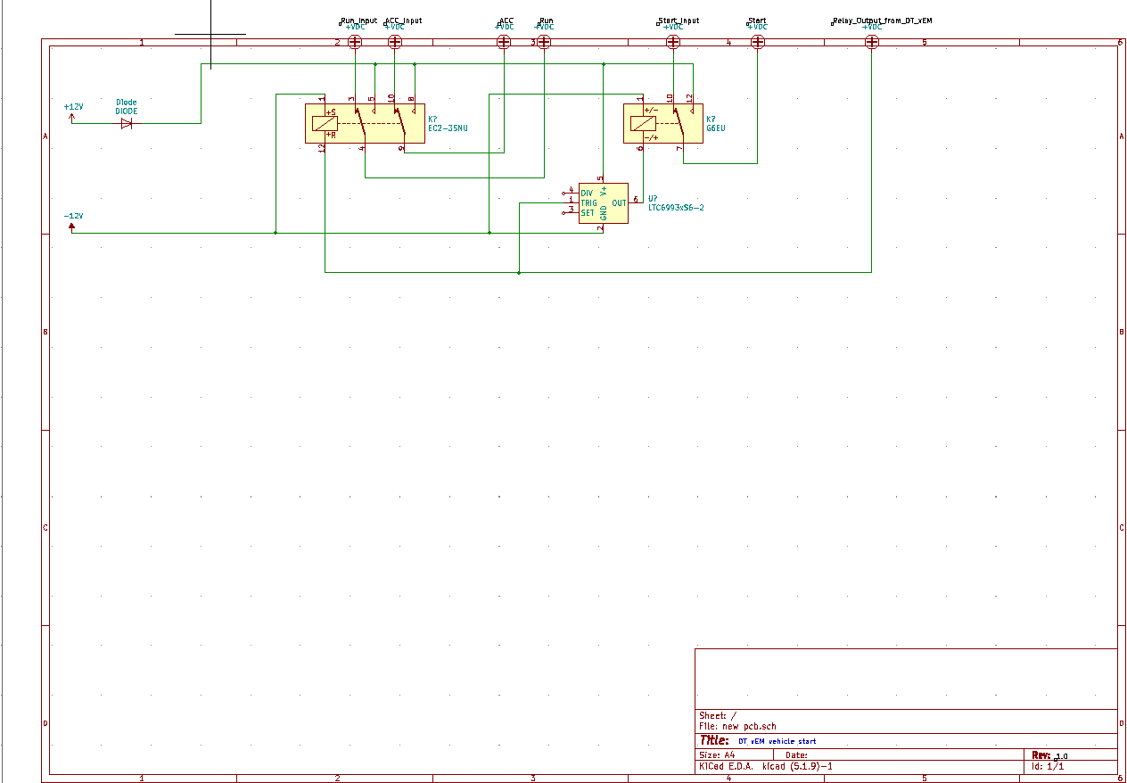
One thing I would note is this: I’m not sure to be honest if the relay on the xAC is SPDT or not. If it doesn’t connect to ground (aka if it’s SPST), I would ensure that you have pull-down resistors on your relay coil inputs, to ensure the input isn’t just floating.

Next, are you certain that your vehicle has both ACC and RUN enabled while the vehicle is running? I ask because on mine, ACC is not enabled at all once the key is past the ACC position in the ignition switch, and if your vehicle is the same, having both ACC and RUN connected could cause issues.

On a similar note, most cars also have a “key inserted” line that I would make sure is taken care of. Again, this is vehicle specific, but it’s something you’ll want to check. For my vehicle, if I was using a solution like this, I might replace the ACC position on the DPDT with the key insert position, as it can be triggered at the same time as the run position.

The biggest thing I wanted to address is the way you’re handling your relays. You’ve connected your start relay to an LTC6993, I’m assuming that’s to handle your start timing? One thing to keep in mind, the xAC does not latch it’s relays, you cannot use it to directly run your run/acc relay in your example. However, you can configure the timing to I believe 1 or 3 seconds using a jumper on the board. So, what I would do, is hook the xAC output to your start relay, and configure it for 3 seconds. That should be enough to crank the engine over.

Then, to handle the run/acc relay, I would probably use a simple flip-flop, with the set pin hooked to the xAC output, and the reset pin hooked to a button that would act as your stop button, connecting to 5V/3.3V.

I would also add a master cutoff switch, as the xAC draws considerable power enough to where I wouldn’t leave it on constantly.

2 Likes

First, put your schematic in the middle of the sheet. The border isn’t there to draw on. It’s there to keep you in. :slight_smile:

I see what you are trying to do, but the big issue with your approach is the output of the access controller is only on for a second or so. So the igntion relay will need to be a latching type and you will have to manage how you are going to deactivate the relay as well. The way its connected now, the ignition relay will turn off once you remove your tag from the reader.

Instead of the pulse generator, control the starter with the tag presence (remove the tag, the starter stops) and then you need a flip flop on the ignition relay.

Also there is no -12 in cars. It’s just referred to as “gnd” for ground.

Awesome, Thank you for the input.

Probably the best person to ask for help. I really like your work.

Nope this is exactly what I was asking for.

Yes, this is what I ment, I dont know what I was thinking.

Will do.

I am making this to be moved from one car to another so I was just keeping the option open for both scenarios.

I did not think about this, I will add for the future.

Yes exactly what I was going for here.

The DPDT relay that I chose for this is a latching relay so it will latch in that position until it receives another pulse from the xAC. I may be wrong and this would not work either, but I will also look at your solution.

Thanks will do.

Using a latching relay is a good idea, but that’s not quite right for hooking it up. The way single coil latching relays (like in your example) work is by flipping polarity on the coil to either set or reset. This doesn’t happen in your example due to the way the xAC outputs. It would just do nothing (you’ve got reset hooked up, it would just reset when given a high input).

Your best approach if you want to use a latching relay would just be switching to a double coil latching relay, it looks like that same company has one available. They’re the more common variety. The relay itself has a set and a reset pin. So, you could hook the set pin up to the output of the xAC, and the reset pin up to a simple button, with the other side of that button connected to your HIGH voltage (likely either 3.3, 5 or 12V depending on what relays you choose, doesn’t matter since you give the xAC the relay switching input anyways).

This would eliminate the need for a separate flip flop, as well as providing good redundancy.

As I mentioned in the prior comment, due to the xAC providing either 1 second or 3 second triggers, you shouldn’t need the LTC6993, you should be able to run the start relay directly off of the xAC output without issues. Several people here have used the xAC in an keyed ignition switch application, and AFAIK that’s the method they’ve all used.

EDIT: To clarify, double coil relays have a set coil and a reset coil. In your example, one side of each coil would be hooked to ground, and the other side would act as your reset and set inputs. This provides a difference across the coil of whatever signal voltage you choose (again, likely 3.3, 5, or 12V. 12 would be easiest, since no voltage conversion would be needed, just a bit of regulation to clean up the power from the car).