I finally got my PN5180 going, I had to go with logic converter on my nano, and I have to say, I’m really impressed about the read range with a full size card (~4in) but the reason range with the implants is disappointing … I have 1/4in max …
I was wondering if anyone ever made cylindrical HF antenna?
Would it be the same as the LF, but a lot less turn?
We need to know how much inductance the coil has. Do you have a VNA or LCR meter? If not can you send me some pretty precise measurements of the dimensions of the onboard coil including the length, width, number of turns and space between the turns? I can calculate that way.
We’re probably going to want to go with air core (not ferrite) to more closely match the passive values of the matching circuit already on the board.
That’s exactly what I was thinking about doing
I was planning on measuring the voltage around the antenna, then desolder the resistors and measure inductance and resistance of the antenna. I’ll post it here when I get to it (probably tomorrow)
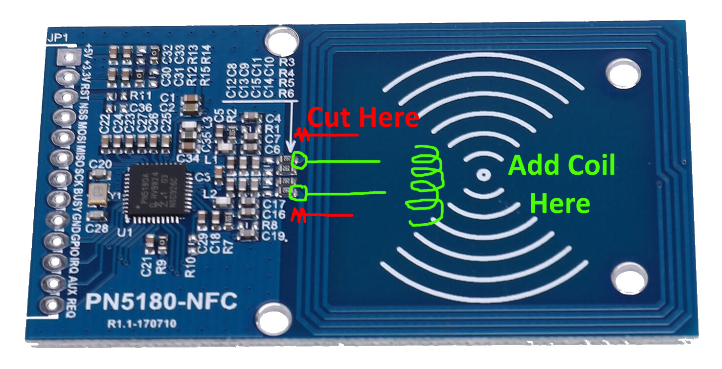
I realize, this is an old thread. However, I have come across the exact same thing and I would like to report on my (very positive) results:
I am using the exact same breakout board as described above. I have cut the two pcb tracks of the coil and attached a simple connector to it. Through this connector I connect a rectangular coil, 160 mm x 240 mm (really large), just one turn. As the inductance of this coil is lower, than the inductance of the pcb coil, I added a parallel capacitor of 30 pF (optimized by trial and error).
The coil reliably detects ISO15693 tags up to 18 cm from the center of the coil.