DIY Microphone Jammer

(sorry about the million edits and formatting, I am getting used to this interface).

I am going to log my attempt to get a DIY microphone jammer working.

Basing off of this repo, my goal is to be able to cancel out a typical smart phone mic within a meter or more.

Reason for project: recently heard about a party host tell how they were able to mediate a dispute amongst guests because they had a recording of their private conversation on their in home surveillance. I was appalled and thought, “there has to be a defense against this”. Some searching later, I found something promising.

Parts needed:

  • Arduino compatible board
  • Amplifier capable of 25-26KHz output into a capacitive load
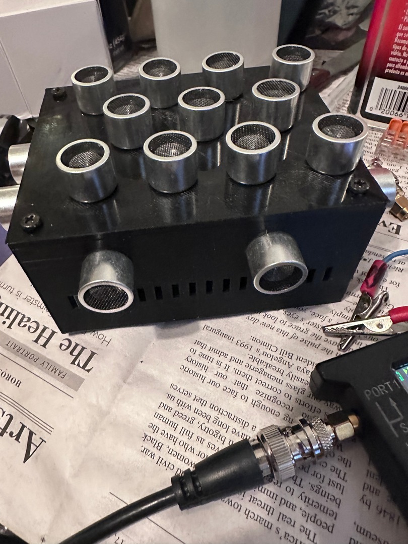
  • 25KHz transducers
  • Various jellybean parts like resistors and inductors
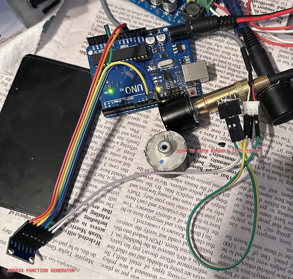
  • Signal generator board AD9833
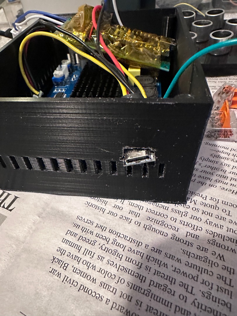
  • Enclosure
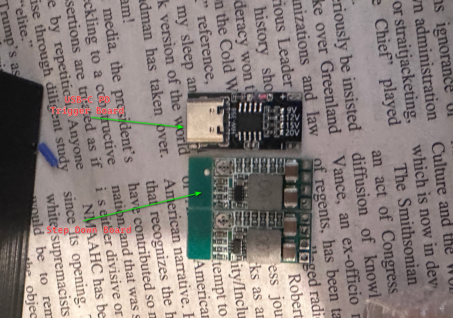
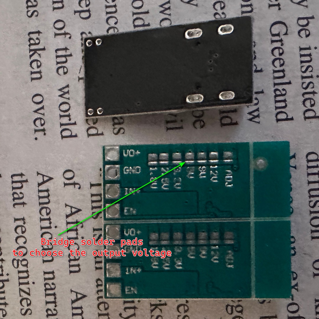
  • Battery pack with voltage regulator and charger board

Tools needed:

  • Oscilloscope
  • Multimeter
  • Function generator
  • Soldering iron
  • Drill, file, etc
  • Test device with microphone

So, first thing is to get the needed parts. I have arduino boards and the jellybeans and battery pack etc, so I needed the function generator board, the amp, and the transducers.

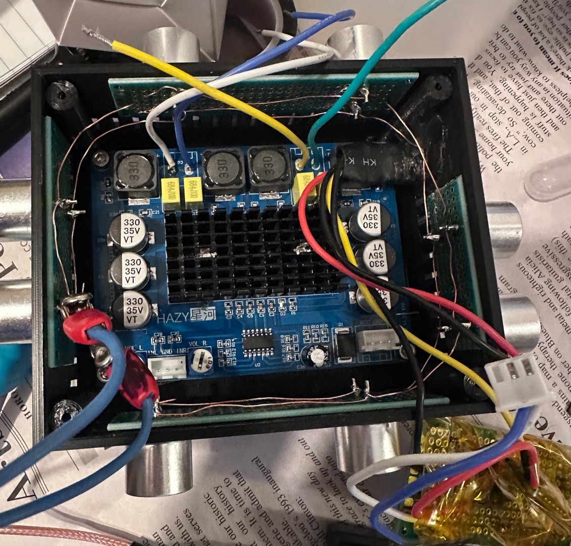
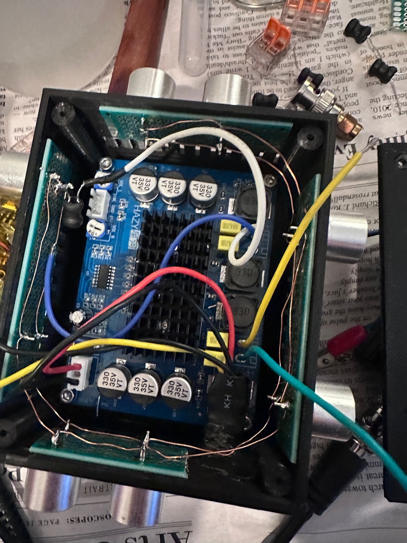
The amp was sourced for $10 on amazon, and the function generator boards (I got a few cause who knows with these things) were a few bucks. But the 25Khz transducers were tricky. Not wanting to deal with Aliexpress and possibly getting hit with tariffs on top of waiting for weeks, I hit the ebays. Was able to source some shady looking surplus military parts at supposedly 26Khz, and decided to take a chance.

First test: Amplifier

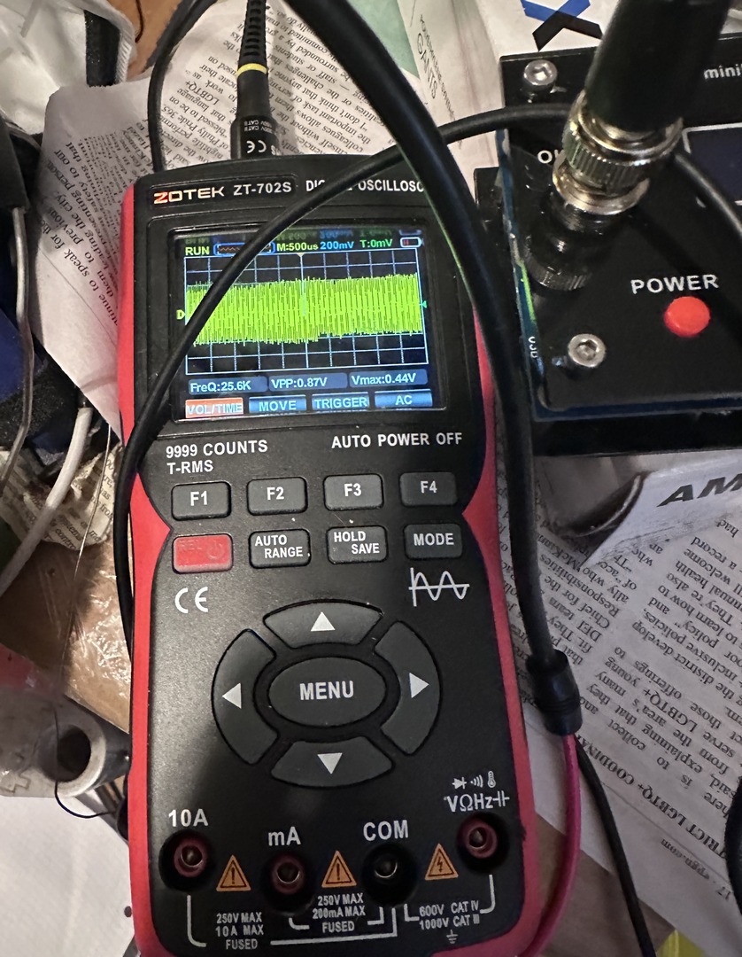
I hooked up the function generator to the amplifier inputs and set it to a 25Khz square wave and put the probes on the amp outputs tied together right and left.

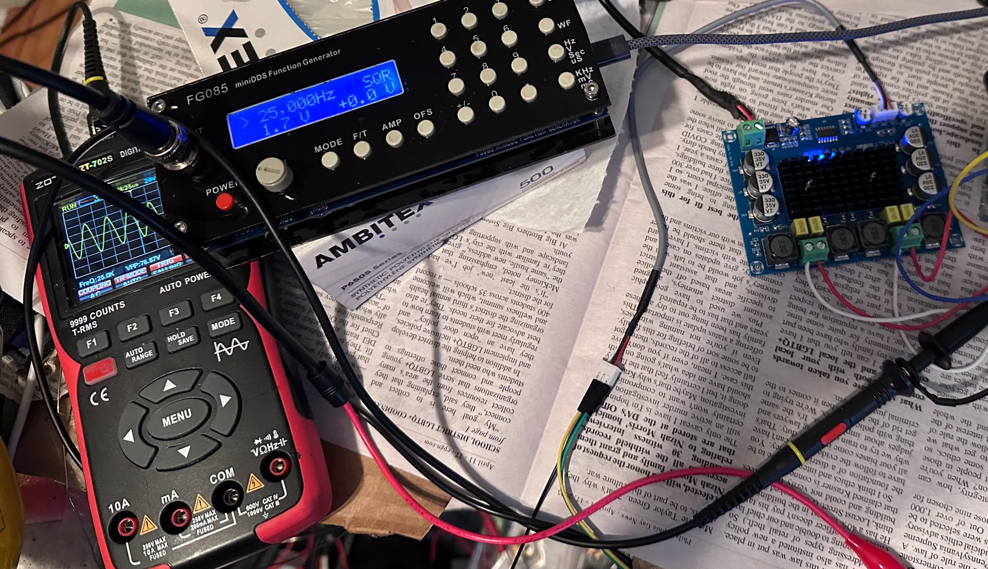
For some reason it is coming out as a sine wave, but I will worry about that later.

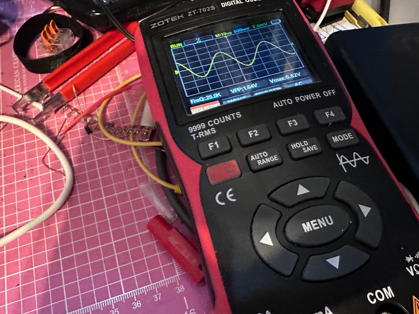
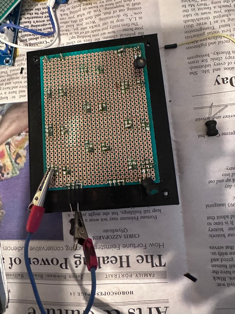
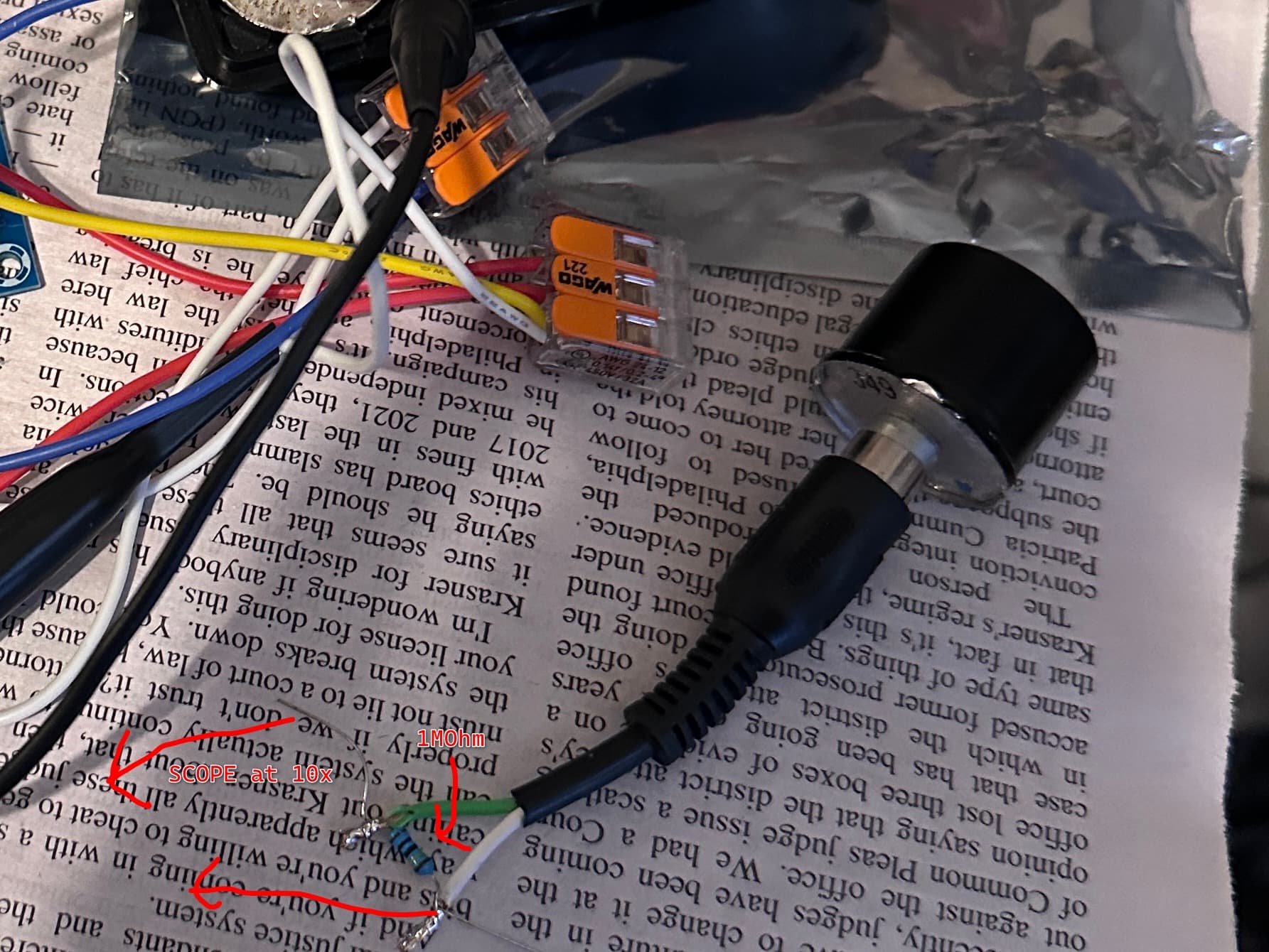
Next I stripped the end of an RCA cable (the transducers have RCA plugs on them) and soldered a 1MOhm resistor between signal and ground, set the probes to 10x and connected them and plugged that into one of the transducers.

I then hooked a transducer to each of the right and left amp output and put the oscope connected one in front of one of them and powered up the amp.

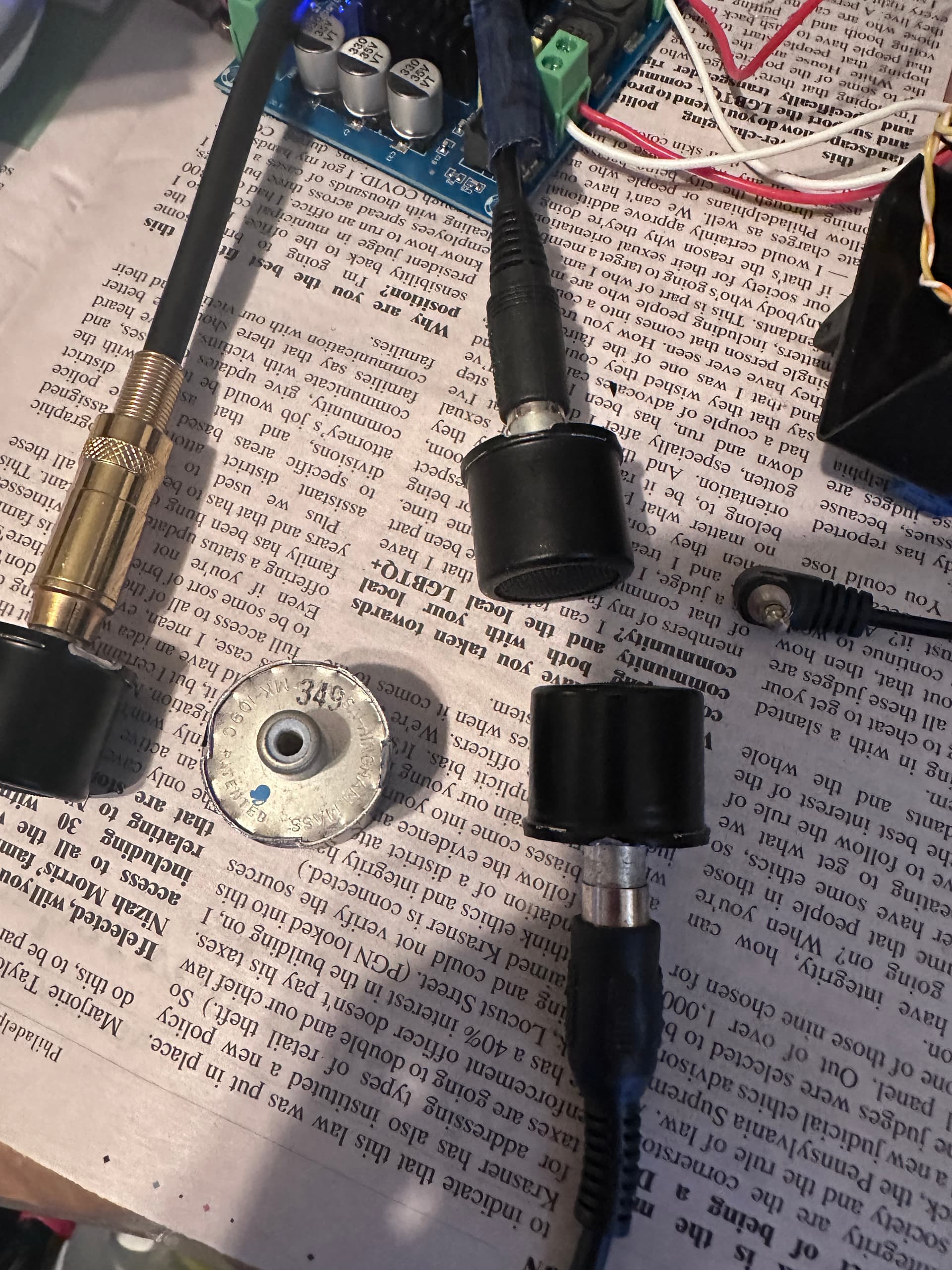
Since piezo transducers can be receivers as well as transmitters, I should be able to hopefully see a voltage at the same frequency on the scope when pointing it at the transmitter.
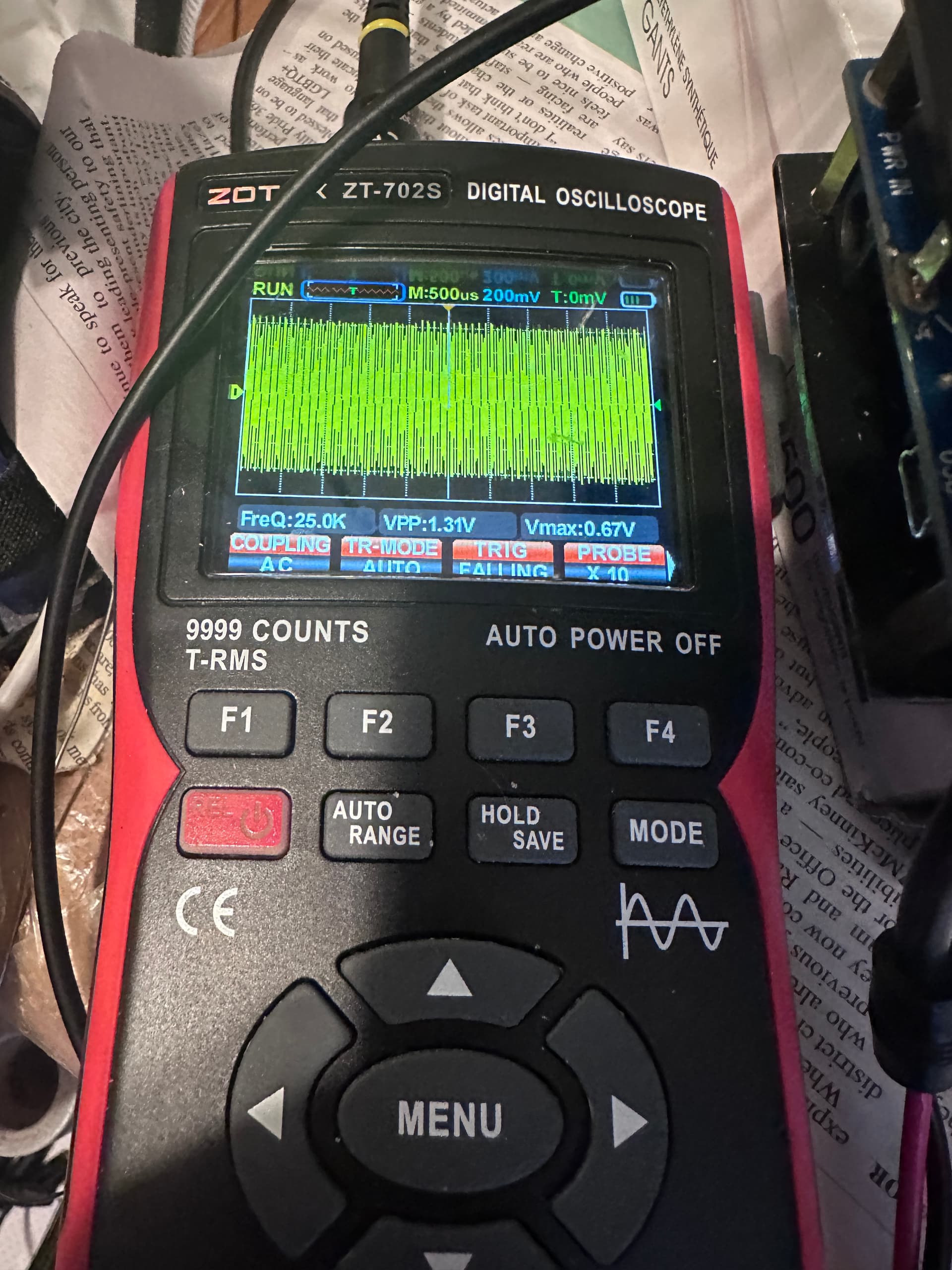
Looks good!

To be continued…

3 Likes

These transducers look like they would be very directional. Meaning you’d get better range but would have to point at the mic. Whereas what you probably want is to cover all directions uniformly?

Just a guess based on the photos, didn’t go through the repo

1 Like

Yes, the spec for them is “MIN. BEAM WIDTH 40 DEG. AT 3 DB POINTS”. Pretty directional. I plan on putting them all around the enclosure.

Hooking up to Arduino

I uploaded the sketch mic-jammer-ad9833-new-version4.ino to my Arduino Uno, after changing the “j” variable in the main loop to 45.

AD9833 connection:

  • 5V to VIN
  • GND to DGND
  • A0 to FSYNC
  • D13 to SCLK
  • D11 to SDATA
  • AGND to AMP INPUT GND
  • AOUT to AMP INPUT LEFT and RIGHT

Amp connection:

  • LEFT OUT POS to TRANSDUCER 1 SIGNAL
  • LEFT OUT NEG to TRANSDUCER 1 GND
  • RIGHT OUT POST to TRANSDUCER 2 SIGNAL
  • RIGHT OUT NEG to TRANSDUCER 2 SIGNAL

I connected the scope to a transducer as before and set it up in front of one of the outputs. It appears to be working.

Waiting for the enclosure to finish in the 3D printer then I will mount a bunch of transducers and test with a mic.

2 Likes

I 3D printed a box and put in 14 transducers but it isn’t getting enough voltage on the amp output to do anything effective, or the output range is wrong. I will probably have to chock the ‘take a chance’ ebay transducers to a loss and order proper ones on digikey along with some IRF4115 mosfets for post-amplification switching/impedence. In the meantime I am going to play with some different configurations and hope I don’t blow the transducers.

If anyone has any experience driving ultrasonic transducers I would love some feedback on this.

Check this out for some hopefully relevant info.

1 Like

That’s great, thanks!

2nd Try:

I ordered some new 25Khz transducers and when they came in I tested them out and they work fine.

These parts apparently are assembled without regard to polarity, so I hooked up each transducer to my multimeter set to DC volts and tapped it. Since piezos will generate voltage with movement I could see the voltage on the meter, and if it was negative, I marked the pin that was connected to my multimeter ground with a red dot, and if it was positive I marked the pin connected to the positive probe with a red dot. This way I won’t get any out of phase cancelation.

Next I printed a lid for a new box and then started the 13 hour print for the rest of the box and mounted the transducers with a protoboard underneath.

I then used my NanoVNA to figure out which inductors to pare with the transducers. The value given on the github repo is for that particular setup, but they are all going to be different.

Basically what you have to do is find the resonant impedance and then add inductors until the reactance value gets low enough and the inductor doesn’t change the resonant frequency too much. See pictures below.


Once I found inductor values for the 4 transducer rows, I hooked one row up to each channel and turned it on.

It is totally audible, it sounds like a CRT that has been left on with no picture, but much louder.

Took a recording with an iPhone. Success!

1 Like

After the box finished printing, I mounted the amp board and cut a hole in the side for the power input.

A note about powering this thing:

I decided using a ready made powerbank was a lot easier than constructing a battery pack and putting in a charger board and a power connector, etc, so I used a USB-C PD 3.1 trigger board instead. They are pretty cheap and you can set the voltage to anything supported by the USB-C Power Delivery spec, and it will send out that voltage as long as the power supply you connect it supports it. Along with that I am using a step down board to power the function generator and the arduino. I set the PD trigger to 12V and that goes IN to the step down which is set to 5V and that goes OUT to the arduino and function generator board.

I mounted the PD trigger board to the side wall using moldable thermoplastic. It comes in plastic beads and you heat them up to about 60C and they turn melty. At that point you can mold them to whatever you like and then they harden and become sandable, drillable, paintable, etc. They are remoldable and will stick to anything else made of plastic pretty permanently. I pre-process them by combining them with color and flattening them and cutting them into pieces for convenience.

Next, I drilled holes in the sides to fit the 8 transducers I had left and soldered them to PC boards and wired them all together in parallel.

After testing with the NanoVNA for the proper inductor I soldered that in series with one of the amp output channels, then put the lit transducers on the other channel with its inductor.

Tested it and screwed in the top.

Conclusion:

It was a fun project, and it does work. It is audible though to people who can hear high frequencies. If you can hear a CRT coil whine then that is you. It is highly annoying. It works for about a meter and makes everything sound kind of like loud encoder artifacts from an MP3 file done at 10Kbps. It will probably also freak out any cats or dogs in the general area.

Would I do it again? Nope.

STL file for printing if you want it:

new_box.stl (89.5 KB)

3 Likes