Hi everyone.
First time poster here - and I need some assistance, as I’m not the most knowledgeable person on electronics.
Handy - yes, knowledgeable - not so much.
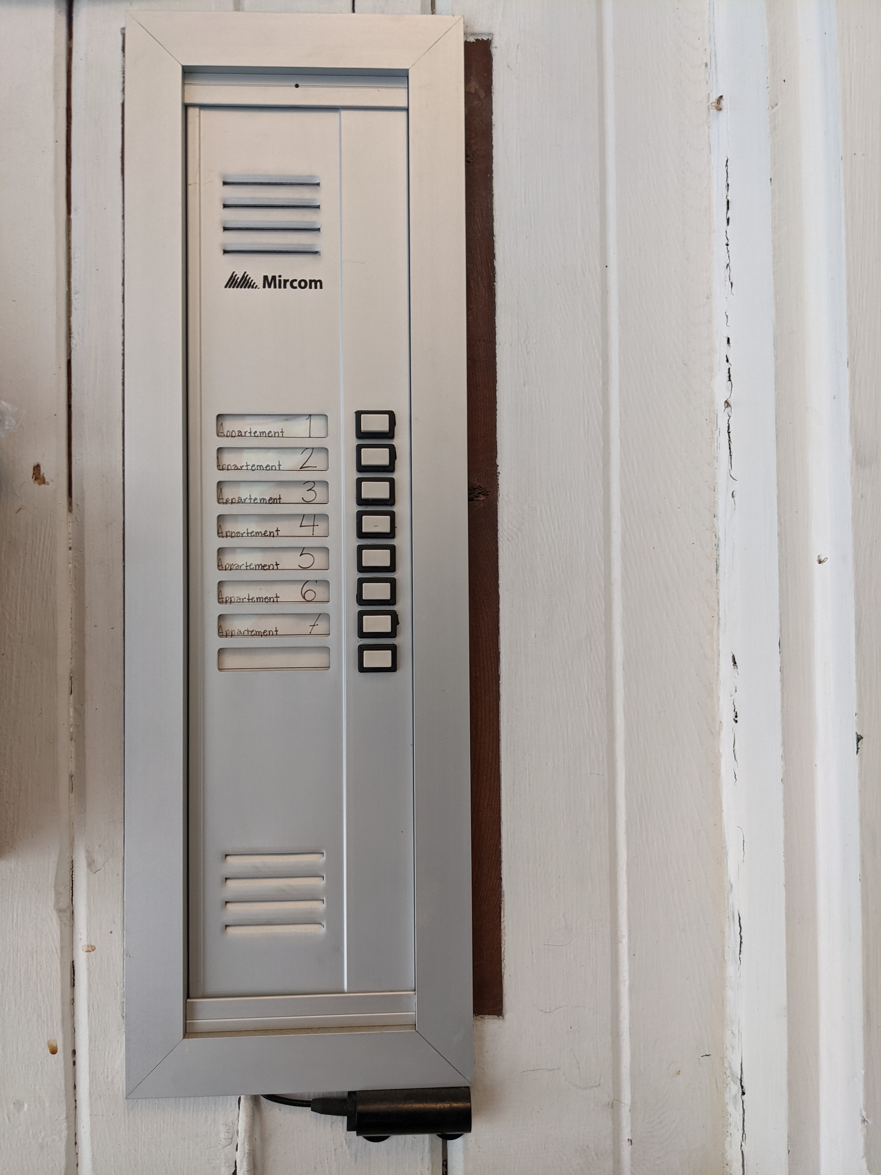
So I’ve got this intercom system, that I use to buzz people through the outside door to my appartement complex. Is it possible to attach my xem access controller, or a rasperry pi system, to “push” the buzzer (top right corner), either via an app, or with a chip implant, from the outside.
I imagine putting up a reader on the outside, and somehow connecting it wirelessly to my indoor buzzer. But is it even possible?
Welcome,
Cool project, I’m sure there is enough knowlege in the community to help you out with this.
Do you have a make and model of that system?
Do you own a multimeter?
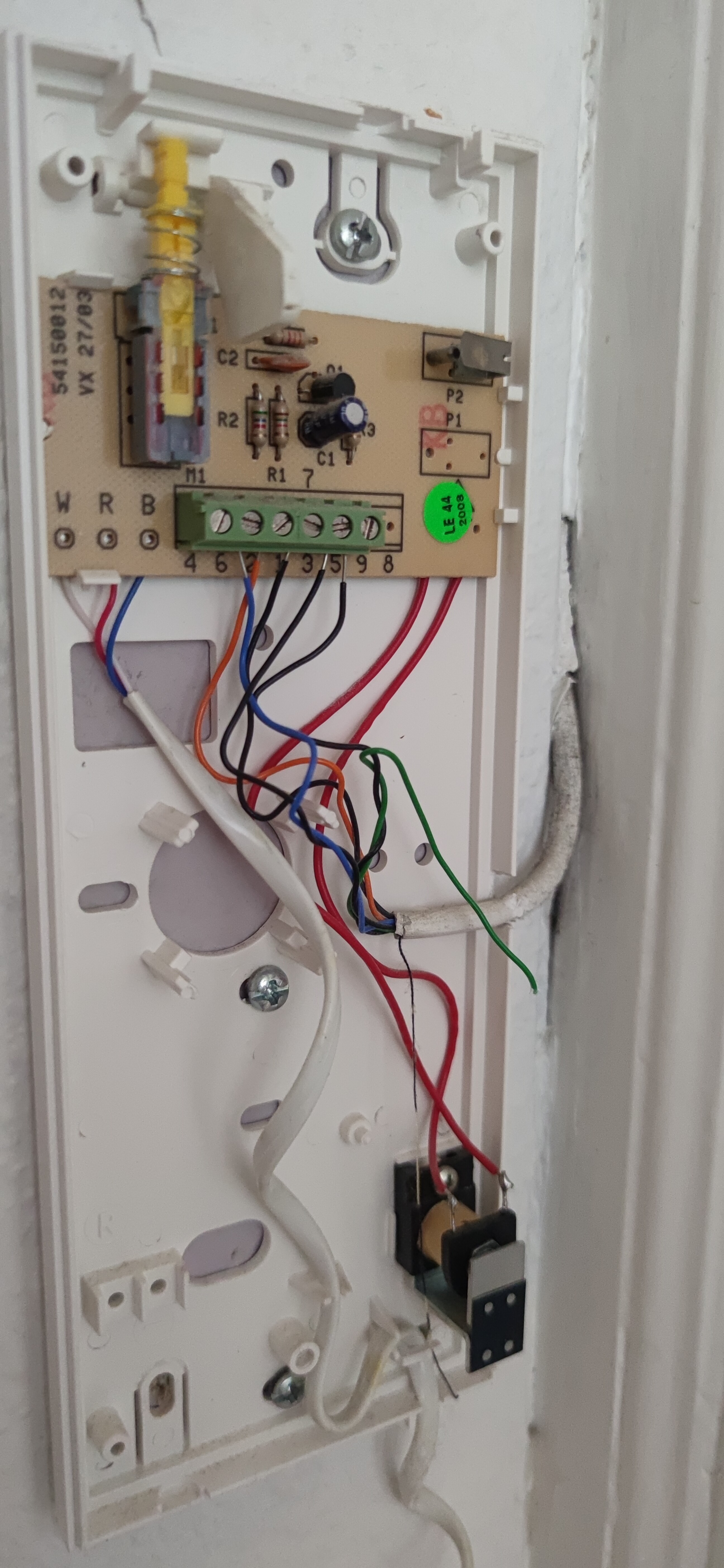
How do you currently press the button? Is the button the buzzer on the top right?
If so , it looks like the 2 red wires go behind the PCB to either side of the “button” / buzzer terminals.
it will be and looks to be Normally Open ( NO ) so you would just need to short the terminals.
Check out this video, it will be the same principle
Sing out if you have some answers or your own questions
I do have a multimeter, yes.
Make and model - I’m not sure what that is haha. Please enlighten me.
On the outside of the plastic casing, there is a button that on the inside, presses down a metal plate-thingy, so it makes contact with what looks like a pin of some sort.
The two red wires going down from behind the plate, looks like they’re e attached to that metal plate-thingy.
They run down to the bottom, to some component I’m not sure what is.
Oh man this brings back memories. Unfortunately not ones that will be that useful. I used to install and repair intercoms like this all around NYC. Handset intercoms were’t as popular as the flat speaker type though.
If you short two of the 5 wires coming from the riser, it will trigger the door open… So it’s a matter of finding which 2…Then connect a normally open relay across those two wires.
The two red wires going to the bottom I believe is the buzzer and have no bearing on this project.
These systems are low voltage and will tolerate momentary shorts on the riser wires. Systematically short every combination of wires on the terminal until you hear the door open. Of course you could also just pull the circuit board and look to see what terminals the PCB traces going to the switch are connected to.
The bigger issue is it does not make sense to put a reader in your apartment as you will not have physical access to it when you are outside the building entrance.
A completely generic white box. Only markings on it is a picture of a key, on the button that opens the door.
The power comes from the side - the white wire hanging out below, is connection to the phone (speaker and mic).
I can’t see any voltage markings. But with the multimeter I can look into the voltages. I am relatively confident using one.
As I’m at work, I haven’t checked the entirety of the video yet. But I will definitely give it a look as soon as I’m back home.
You will not be able to power anything from the riser wires. There is no power to be had (other than when someone presses the button on the panel outside power is sent to the buzzer), just audio signals and input that will trigger the door opening. It’s all low voltage. 4 of the 5 wires are the same signals going to all the other apartments, with the 5th being unique to your apartment (buzzer). Loading them down in any way can affect the whole building.
I’ve considered a few different things.
Here in Denmark, it’s very popular to have extra keys, locked in a small box outside, with a number-code to open the box. So I considered mounting one of those, but fill it with batteries instead of keys haha, and have a reader on the side or bottom of it.
Unfortunately the amount of batteries that would fit in a box like that would only power the reader a few days, if that. I supposed you could put a switch a momentary switch on it so you press the switch with one hand to power it up and scan your tag with the other. That could work assuming you weren’t using a Pi for the wireless part otherwise you’d have to wait for it to boot.
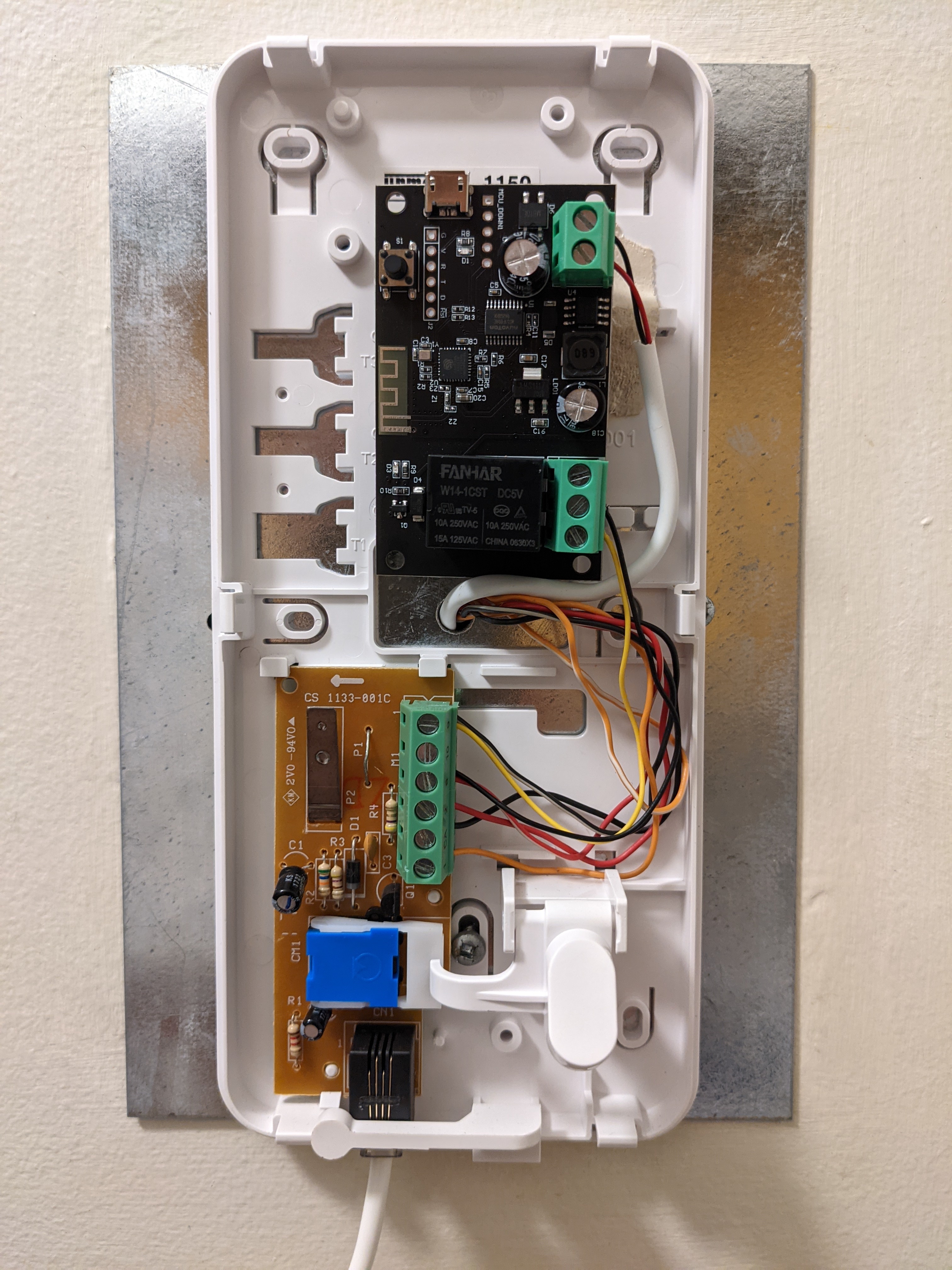
While not as cool as in implant, if you could reach your wifi from the front door, I could see a more reliable solution of using your phone to unlock by accessing a pi over the network that is running in your apartment connected to a relay connected to the door button on the intercom. The pi could be running a web server with a web page that allows you to control the relay.
It works on 16v AC. So the thing was to put a small transformer to bring it to 12dc, find the “unlock” terminals, add the xem controller and find a way to have the antenna outside. It all fits neatly right in the standard box.
Then my girlfriend wanted to enter without keys too. The thing is, she doesn’t have an implant and doesn’t plan on having one.
So yeah. I added a “wifi relay” directly in the phone. It is back to back with my microwave. So I drilled a small hole in the wall hidden by the microwave and added a small cable to bring the 12v needed. And that’s pretty much it for unlocking the door with her phone.
Edit: I think I fond your specific phone. The pinout should be:
4 Electronic Call
6 Call AC
2 Speech In (Speaker)
1 Speech Out (Mic)
3 Common
5 Lock
Tell me where you plan to go from there and I’ll do my best to help
For a moment I thought that it was a proper microswitch. However, it’s clear that they use the cheapest available contacts to make a switch. In a worst case scenario you could just tie two wires to the contacts and hook them up the the contacts of a relay. However, it’s best to find the correct screw terminals. And from the datasheet I found, they appear to be the two leftmost terminals that are marked 3 and 5.