Endochron Implant

Patenting things is rarely the path to success. It’s very difficult and mostly for show. If you want to try though feel free to give it a go. It’s costly so don’t expect an ROI

It won’t be an issue because this is a publicly published project and counts are prior art, so nobody is going to be able to patent and if they attempt it we can challenge.

3 Likes

Actually just today, I heard of someone who patented someone else’s invention, then tried to sue that person’s employer for patent infringement. Unfortunately they screwed up and listed the original creator under “prior art”…

Strange how these things all come up at the same time.

2 Likes

OK, got some emails from the licence people and Widetronix I’m about to read, my caps, magnet sensors, RTC and displays have been shipped so I can start prototyping soon, and I had a go at some CAD of the circuit board, would love some criticism:
Are the vias ok? what do you think about making solder pads vias re. Amal thought they might be causing problems?
The purple is cut lines, I’m thinking of countersinking the big parts, is that worth it? What about parts on the back?
Would a ground plane ruin the RFID strength (I left it out because I thought so)? And how on earth do I can someone else calculate the antenna size?


Here are some SVG format ones, split into 2 layers as well. Download them though, the drive viewer doesn’t show them properly. @amal can you let us upload SVGs?

NOTES: Parts will probably change, I know I can make it a bit smaller, this is just for practice really.

5 Likes

What are you planning on doing with the ntag i2c? Storing time data?

General Recommendations:
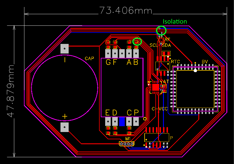
Be careful to make sure there is enough isolation between traces that carry different signals. Usually a design rules check will catch these, but the DRC needs to be set up correctly for your fabricator and you have to not override them. I would also add two Through-hole pins for external power and ground to aid your testing. You may also want SMD footprints connecting the SDA and SCL traces to power as pull-ups, Just in case it’s difficult to set internal pull-ups on the ATTiny.

Your Questions:
The vias for the antenna are a bit close to the antenna traces, there might be shorts. You always have to plan for manufacturing tolerances. Via-in-pad is generally acceptable, but it does require an extra processing step during fabrication. Often for the lowest cost PCB deals the fabricator will flag designs with via-in-pad and say you can’t do that. Otherwise you need to message them back several times in the middle of the night and fight it, or just pay more.

For test boards I would always make the board way bigger than you need to give you room to work with and troubleshoot, then you can miniaturize in another revision. Since none of these will be implanted yet don’t make your life more difficult (and expensive) than it needs to be. Personally I would make the board outline larger and make the two ends half-circles. You can usually make two arcs with radii that are half the width of the board to create half-circles. Countersinking usually means carving a 3-dimensional divet in the substrate to allow parts to sit flush. In this case the design is only 2.5-dimensional so you would just be making holes. I don’t think it’s necessary in this case, just make it a solid board with the parts sitting on top.

A ground plane would block the flux in the center of the antenna and also add parasitics that would throw off the tuning. Almost universally I add a ground plane for normal boards, but never add one for RFID boards.

I can calculate the antenna dimensions for you using this calculator I published. It’s not perfect, but it will get you very close. You can get even closer if we undershoot the inductance for the antenna and you add a footprint for an SMD capacitor in parallel with the antenna pads on the NFC chip. If you want more information on this process you can check out this thread. I’ll get back to you on that in a few minutes.

I think the plan is to use the NTAG I2C Plus to communicate with the ATTiny and set new time values that it will then relay to the RTC. In the original Endochron design concept we planned to use an NTAG 5 with a transparent I2C master channel to skip the MCU entirely, but this will do for now since it will be easier to set up for testing.

3 Likes

NTAGI2C_CoilDim

And here’s the antenna laid out in eagle. You don’t have to use this for anything if you want to use a ECAD program you’re used to, it’s just good as a reference.

EAGLE_NTAGI2CTestAntenna.zip (3.3 KB)

Thank you :relieved:

2 Likes


Left is a 15F and a 4F capacitor for testing, any suggestions on how to over-volt test them? I can do 30v 3a DC, or 240v AC? And I’ll do some instant discharge tests as well
Second is the displays I’m thinking of, then the others are an RTC and magnet sensors for prototyping

1 Like

Gonna have a hard time stuffing that into an injector syringe.:joy:

2 Likes

Why would you want to do that? You can just go off the datasheet for their breakdown voltage. They’re never going to be above 3.1V in this use case.

Stress testing one by charging it up and then shorting it out with a timer relay module would be interesting. See how many times it could withstand a short and how dramatic the pop would be. That would basically just be for fun though because if the implant experienced a short it would never be able to charge again to fail twice.

You should definitely measure the equivalent series resistance (ESR) with a meter, and see if it matches the datasheet.

What would be most interesting would be a self discharge test to see how long it could hold a charge. Basically you hook up a DC power supply at 3.1V, and also hook up a multimeter with some crocodile clips to measure the voltage of the cap. Turn off the DC power supply and write down the measured voltage every minute for 10 minutes, and then every 5 minutes for 20 more minutes. After that, check it every 15 minutes until it’s about 10% of the original voltage (the last 10% could take many hours so don’t bother recording that).

2 Likes

This is quite promising, I ran all 7 segments from the cap and it lasted about 15 minutes, or till 1.75v (here’s the time-lapse)
I’m doing another one of the charge loss rate now. The cap doesn’t seem to lose much charge if I short it, maybe it’s just got a slow discharge rate. I’ll measure the short circuit current soon.

2 Likes

Ran the charge loss for 5 hours, it’s been at 2.44v for 3 hours EDIT: 16 hours REEDIT: 28 hours. Here’s the other videos, and Here is my folder of documents related to the project

Can someone tell me approximately how much current we can get through NFC? Does anyone have the NTAG I2C test card they can do some experiments on power delivery with? I’ll get one with my REDACTED join the DT club :stuck_out_tongue: but that’s at least a month off

Wait, what?!.. Please tell me there’s an awesome story behind this innocuous little sentence?

1 Like

Good god! I don’t know what’s worse. People selling this crap… Or people buying this crap.

200 (3)

4 Likes

This video is also really good, by Thought Emporium, feat. Amal :slight_smile:

I saw this video 8 months before I got my implants, and I had completely forgotten that Amal was in it. Freaked me out when I watched it a few months ago.

There’s a follow-up too:

4 Likes

What’s funny to me is I trust the xGLO more than I do the metal container since I can’t see this being long enough lasting to reliably last anywhere near it’s meaningful life.

Still, I’m excited about the possibilities!

does anyone have an idea of how to make the power control circuit? my current design (that I don’t like much) is an SR latch made with 2 nor gates, set is connected to the magnet sensor (probably through a comparator) and the microcontroller sends the reset signal when it’s finished the program. the RTC would be separate from this circuit meaning it’s powered all the time.

Problems with this are that it’s a custom solution so not 100% reliable in itself, it is possible for the MC to glitch and not send the reset, and I’m not very experienced with this so I don’t trust myself :slight_smile: