Community Project: Endochron
Anyone who would like to contribute feel free to add your thoughts here. If you need to make purchases to support your contribution to the project, see this thread , and direct message @amal or @Satur9 with details. Project threads can get a little out of hand with tons of people brainstorming. I ask that you limit your messages to the topic at hand. Try to condense multiple messages into one post.
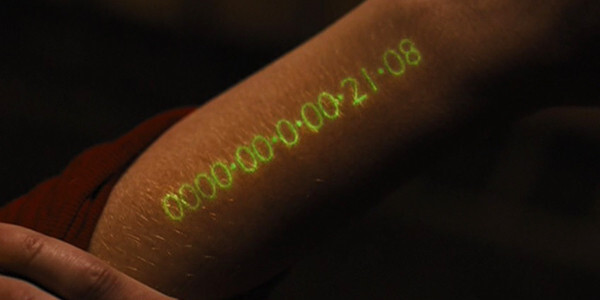
This community project has been ongoing for awhile but the part sourcing has been a huge hurdle. The current goal is to use surface mount betavoltaic cells to power a semi-permanent internal clock with a red LED 7-segment display.
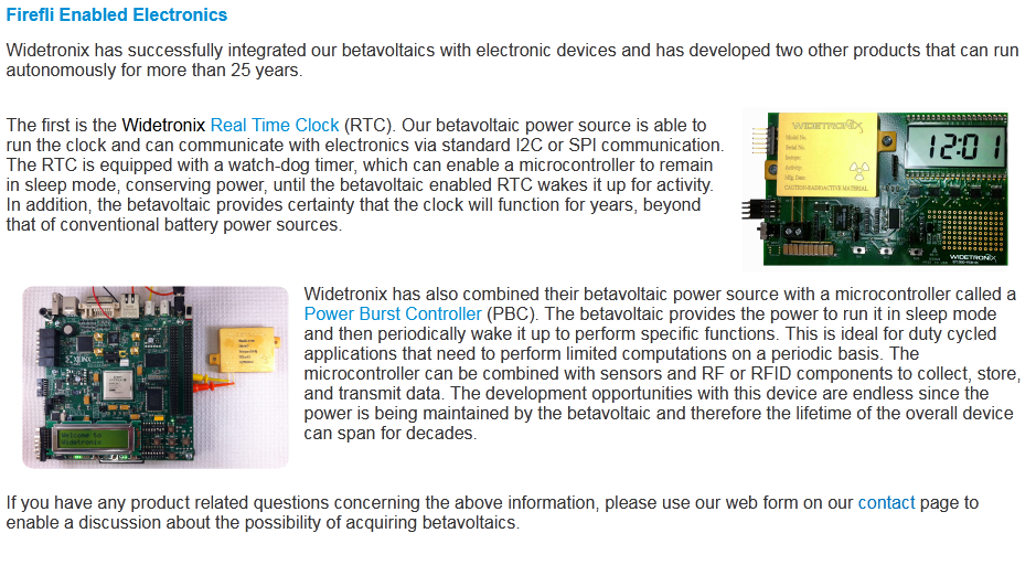
Unfortunately the biggest hurdle is actually getting your hands on suitable betavoltaic cells. A few companies like CityLabs and Widetronix offer surface mount versions of their products. The problem has been actually getting them to talk with you, and the large upfront capital investment. Fortunately, Widetronix has optimized their production to the point that medium batches of custom SKUs are plausible.
I am in contact with Chris Thomas (CEO of Widetronix) and I am working through the process of getting a surface mount package produced. The output is abysmally small, but for an implantable clock where the LEDs are only lit for a second a few times a day it should be doable based on our calculations. Here are some of the specs on the proposed unit:
12 years half life of tritium
8mm x 8mm x 2mm package dimensions
2uW output (3.8V at 526nA)
Even if you don’t particularly care about the implantable clock use-case, these betavoltaics will become available for other biohacking projects. The current plan is:
NTAG 5 acting as a transparent I2C master bridge between the phone and a low power MCU+RTC combo
Betavoltaic cell (possibly several in parallel) trickle charging a capacitor bank (possibly regulated by a zener diode). The energy harvesting on the NFC chip can top up the capacitor bank if needed.
Surface mount 7-segment display hooked up to MCU to display clock digits sequentially (lower power version could use single indicator LED with binary clock)
Some next steps are:
Source appropriate low power MCU+RTC combo
Acquire radioisotope license (Satur9 working through that process)
Any idea which MCU/RTC combo you are thinking of using?
I have begun playing around with Arduino stuff recently and am certainly willing to try and implement a few display mechanisms. Are you thinking one digit display or multiple digits?
We’ve been searching but haven’t found any ideal candidates. Widetronix has sample products that are exactly what we’re looking to do, but I can’t get Chris to give me any. They must not keep them in stock like dev boards. If anyone can find some kind of BOM or analyze the pictures to determine what parts they’re using that would give us somewhere to start.
There is a bit of a difference between betavoltaics and a glass vial full of tritium and phosphor, although the products themselves do not appear to be pre-approved for medical uses.
Edit: Having said that I personally would still be cautious about the use of them without some further testing.
Right, but has anyone tested their actual durability?
This, I think the concept of beta voltiacs are super cool and promising… and even though I was personally mostly willing to do an xGLO, that’s because I work with tritium vials, so I had a bit of faith in the construction
Beta voltiacs I have no understanding of how they are realistically constructed
Well, it’s not too difficult, I have working code that takes the time from an RTC module (DS1307) and displays the date and time one digit at a time on a seven segment display connected via a 74HC595. I am using a Uno as the microcontroller at the moment. I am using I2C to talk to the RTC and three digital I/O pins for the display. I am not displaying seconds as the time taken to cycle through the date/time would make it inaccurate.
The only remaining issues are how to trigger the display, and how to set the RTC in the first place.
Triggering could be done by simply running once on power on and then shutting down, but something still needs to power it up.
The real issue is getting the the whole assembly to run reliably on 526nA that reduces by half every 12 years. It’s not a trivial matter. Your build is probably consuming several mA and even in deep sleep mode you’ll only be able to get it down to uA range.
For triggering we were hypothesizing a few strategies. Since everyone doesn’t have a magnet to trigger a hall effect sensor we were leaning towards a surface mount vibration sensor to trigger an interrupt and wake the device.
I was thinking both triggers and letting you configure it somehow would be cool if we could. Then for the people with magnets (I assume most people putting something this crazy in would have one or be willing to add one for a more controllable trigger) could use the magnet but obvs not a priority.
The communication for setting it up and updating it will be posible via NFC using the NTAG5 as a I2C Primary bridge as mentioned here:
I can see if I have a suitable sensor to implement such a trigger.
I am not a hardware guy, but I can do software. The point wasn’t to build a working hardware solution but to prove the software solution. Drivers will probably need to be replaced, but until a hardware solution is ready this can prove the interface. The date and time is readable but I think you might want to consider how much info you really want to display.
I will try and record a video of my current display just to give you some idea of what the display could look like.
So here it is, the RTC is set to UTC at the moment.
I have ordered an NFC/I2C card from DT so I can hopefully add the functionality to set the time on the RTC through that.
What you see is the upload, followed by the app starting and displaying the date/time one digit at a time with a pause between the units. (2021 08 27 19 06) I realise that this doesn’t help with the hard part (the hardware) but if I can at least help with the software side…
If I can get the NFC/I2C interface working for configuration I will then see if I can add display configuration options too. (Don’t display year/month/day, display a separator (- or _?), and so on)
If the equivalent of a 74hc595 is too power hungry, I can switch the display functionality to drive the seven segments directly, but that will change the requirements on the MCU.
Thanks for testing that out. The LED display will be common anode, so the MCU will only need to sink current from the capacitor bank, not source it.
It’s difficult to wrap your head around how little power we’re dealing with here. Suffice it to say that we’re going to need to find a very specialized IC to manage this thing at such low power. I’m hoping we can locate an extremely low power RTC+LED driver IC with a small built in microcontroller or state machine that can be reprogrammed completely over I2C with the transparent master mode available in the NTAG 5 chip.
If we can’t do that we might be at an impasse, because that build you’re using right now is probably drawing about 40mA, which is 800 million times more current than we can source (if we only use one betavoltaic cell)
I think that display format works, although personally I would consider dropping at least the month and year.
Yes, a lot of this will need rewriting later. I am tempted to see if I can use the I2C card and a much smaller micro controller (I have an attiny85 and an adafruit trinket m0 sitting around) to drive the display from a phone (without an RTC). Not as useful as you would be using it as a display for the phone, but getting closer to the goal sans betavoltaics.
The trinket can achieve 40μA in sleep mode, while the attiny85 can apparently achieve 5μA. I need to dig into the datasheet to see if they have sufficient pins. I realise this is still more than you want, but getting closer.
I2C+ test card arrived, I think the digikey (attiny85) has enough I/O lines for a test build.
I think I will be working on that this weekend. Switching from common cathode to common anode should just be a case of flipping bits.
I really don’t know where I can source lower power parts, but I can certainly turn off parts of the attiny85 to reduce power consumption. I don’t know how much that will help.
Is there a specific repository location for this project? If not then does anyone have any preferences (GitHub? Gitlab? Somewhere else?)
Has using Solid state smd batteries instead of a capacitor bank been considered they’re pretty much made for this kind of incredibly low power application, have a look at TDKs ceracharge or Cymbet Enerchip.
We can muster more than 100uA as long as we give the capacitor bank sufficient time to recharge. My target is 3x a day cycling through the 4 digits in the span of one second. I’m confident we can do better than that, especially with the increased output of the cells during the first few years and the possibility of topping the bank up to 3.1V with the NFC interface.
I’ve had a quick look around and it looks like the PCF2123 from NXP is the lowest power RTC I could find, it draws 100nA.
I couldn’t find a low enough power microcontroller with a quick search though. It’s quite difficult to search for one with few enough features and a low enough clock speed to fit this use case.