Finally made my car implant compatible

That would be my first test

  1. Remove transponder from your key,
  2. leave the transponder in the car right by the ignition.( around the ignition barrel )
  3. Lock the car
  4. Wait a period of time
  5. Unlock the car
  6. Start the car ( With the transponder still in place )
  7. If it works, you should be golden!

Obviously I’m not familiar with your car, but the handful I have dealt with, your process sounds more extreme than I would have thought necessary.
Remove the steering boss/shroud
You should find somewhere on the barrel housing a small metal detent
Use a screwdriver or similar to depress the detent at the same time
insert the key and turn it to ACC or on.
The detent should “give” and you will be able to remove the lock barrel.
TA DA :mage:

Around your lock barrel shroud you should see the immobiliser antenna, which is where, IF your transponder test from above worked, you will hot glue / tape your transponder in place.

The hole where your key barrel was, Is now where you can mount your Push to start button.

HOPEFULLY, this process makes sense and more importantly it works for YOUR current setup.

If not, let us know how your testing goes, and maybe start your own thread in the projects section, talk us through your findings, and hopefully through the community somebody will be able to help.

1 Like

So in the diagram I’m planning on powering both the latching spdt relay and the spst relays all 3 with the signal line of the xEM access controller (xEMac) , that way when the xEMac signal line goes low and stops sending 12v+ then all relays are unpowered. Therefore the only device drawing power is the xEMac.

Or should I maybe not drive all relays with the signal line?

2 Likes

No, right you are, Good catch…Relays only energised when your xEM/NExT is presented.
Therefore your only current draw should be your xAC of around 11mA
:+1:

1 Like

Hey do you mind explaining like I’m 5 how to use transistors and optocouplers for this?

Must have spent couple hours reading stuff about how they work and what not over at sparkfun.com but still don’t understand how I could make a latching relay with them.

Also how would I wire the thing together?
I assume some wizardry with the transistors to make a latching switch, and then the optocouplers for actuating the keyfob? But they seem complicated needing to add resistors and capacitors and what not apparently…

Thx for any help. I think it’d be best to fit everything inside the xEM access controller, but if I can’t figure this out I’ll just use big clunky relays.

2 Likes

I will do after work, I’ll use this as a place holder till then.

EDIT 1:
I havent forgot this, I will be ordering an xAC tomorrow I’ve prototyped a circuit that appears to work. I’m also gonna design a little PCB as an add in for this purpose. It will be completely open so anyone can order pcbs for any supplier as long as there competent at soldering.

3 Likes

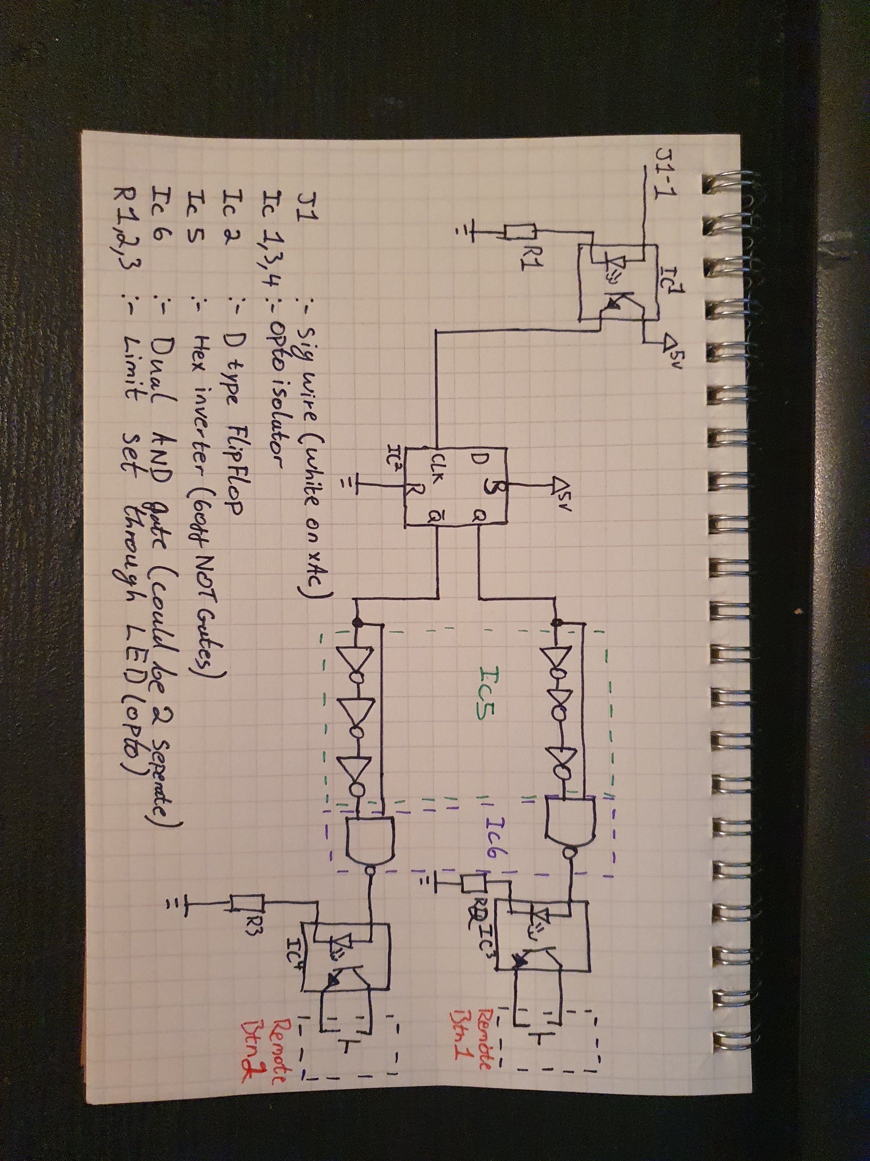
Right this is the circuit, it works in principle I’ve driven LED’s on the outputs and the blink very quickly (may be too quickly).

Hopefully the circuit makes sense any questions I will do my best to answer.

1 Like

I see you too, are a proponent of AppleCAD™ :wink:

I might have to add your plans to my project to do list…

I hope it works well for you @ChildApple

1 Like

Can’t beat a quick sketch.

Any who I’ve gone and done a board, I’ve kept it as small as I can without making the soldering too difficult. Board measures 25 x 28 mm, I’m going to order a handful once they arrive I’ll put them together an we will see what happens.

P.s. at this size more than capable of fitting inside the xAC.

P.s.s. believe the board can pick up 5v from the xAC controller board but am unsure on current consumption (how much over head is available in the controller) worst case a 7805 tacked inside will do the trick.

3 Likes

Love your work mate.
Great stuff.

1 Like

Same deal here. I have a Crown Vic. No immobilizer, no chipped key. I eventually want to make it chip based but I don’t have the time and I also need to fix the car up before I do that.

3 Likes

Wow, this is so much better than I had any right to expect.

Kinda understood most of it, now to find the correct components lol. Like no clue what IC5 is or does. nor where to source them

Are you planning on building the actual board? Who will you have them print it?

My soldering skills are meh but i think I could get the board together.

If you some made I’d love to buy one from you.

Maybe you could have a market here if you sold the boards, make it way earier for people to wire up their cars with an xem and a key fob.

Anyway thanks!

2 Likes

If you’ve got questions ask I’ll help as much as I can

IC5 & 6 are AND gates basically the give an output only when both inputs are high, turning our out to a pulsed out.

Yes!

Once I’m happy it works as expected I’ve got no problem selling them at cost.

Hopefully! Well that’s the idea anyway, potentially offer a kit of parts (pcb assembly), a kit to fit to car (some t taps, pcb and short wires for inside the xAC or even pre modes xAC controllers.

Ofcourse everything will be open source so it you want to source pcbs and parts on your own your more than welcome.

3 Likes

if you want to work through us we would buy them from you at a bit of a margin and sell them as an add-on for the xEM Access Controller. Selling for literal cost can be tough to quantify when it comes to labor times, handling, packing, shipping labels, etc… so we encourage at least a little margin.

We also want to encourage the idea of streamlining our own community’s ingenuity to bring much needed things to market and make them available and affordable… if DT bought them in bulk we could arrange a lower manufacturing price to offset margins to reward the design and retail chain.

Thoughts?

10 Likes

I hoped (but actually knew that would happen) either way… well done community!

3 Likes

Wow, never though that would be an option. Once I’ve hammered out any issues I will definitely open up those line to you, if I’m honest once I’m happy I would probably say something like chuck me some hardware and you can have all the data you need :grin:

I’m not “in this” for any gain I would quite happily hand over the production to you fine people.

5 Likes

Got board, see what I did there :slight_smile:

Have changed the layout of the board even smaller now.

And found a great place for it to sit!

3 Likes

Is it 2 layer?

1 Like

Aye, but only 3 R’s and a ground plane.

i have absolutely no idea what’s going on with all these circuits but i can tell good things are happening. go team and go @Devilclarke!

tenor

7 Likes

Would terminal blocks drive the cost up too much?