So finally got around to wiring my car to the xEM controller.
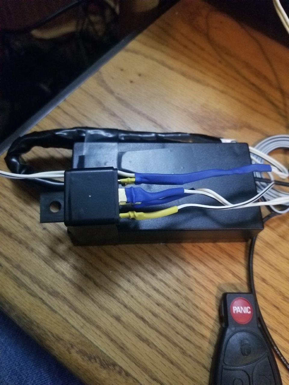
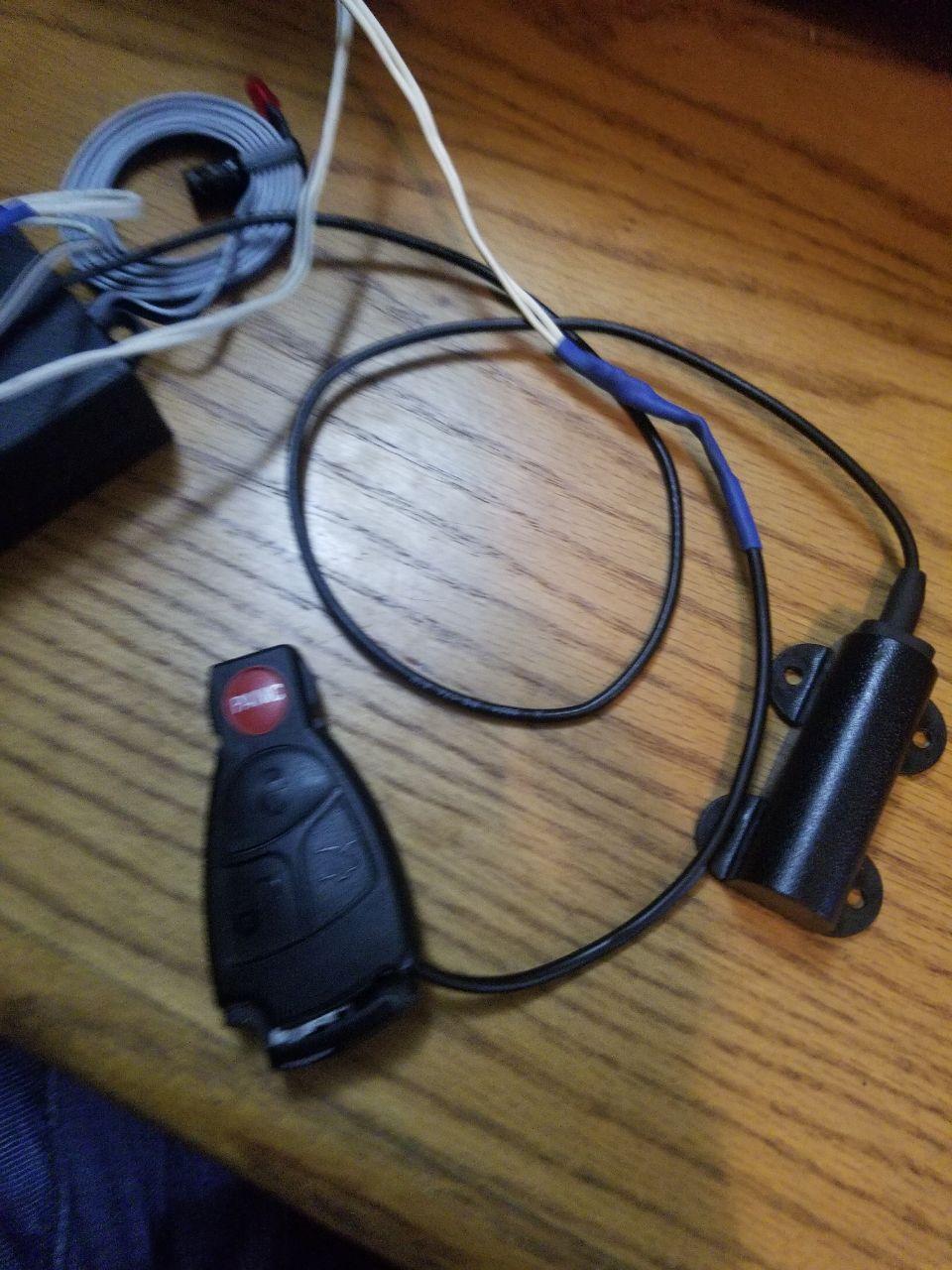
So because my car doesn’t like to play well with others I had to get a key-fob to use for the project
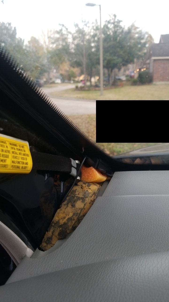
The goal here was to be able to use a NExT to unlock my car. And to be as low profile as possible. Essentially nothing should be visible either inside or outside the car.
I achieved this by connecting the xEM to my car ground and a unused fuse slot on the fuse box. the signal wire actuates a common automotive relay, The relay closes the circuit to the key-fob’s “Unlock” button which I soldered some wires to.
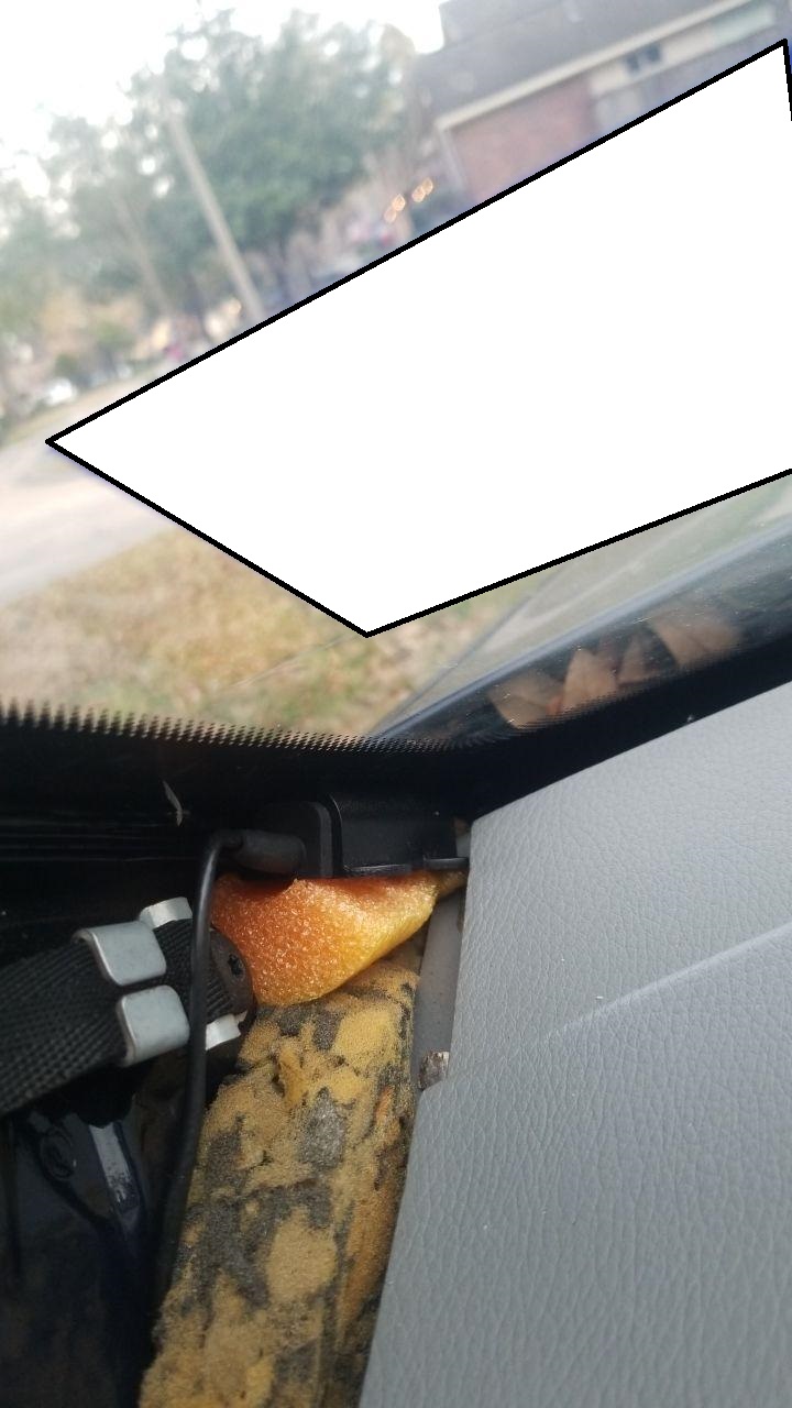
All is hidden inside my dash in some empty spaces.
And the reader is inside the trim behind the black part of the glass.
it can still read no problem. and nothing is visible form the outside.
Future Goals; Originally I didn’t care about locking the car. Since I thought I’d be able to use the button in the car and then close the door. But if I do this, the drivers door won’t lock. Only way to lock it is to use the keyfob or the mechanical key, sigh.
Anyone have any ideas on how to be able to use the same xEM access controller to “push” both buttons? Ideally it could alterante between pressing one and the other.
some pictures of the installation, and the xEM with the wiring done.
You would probably have better luck getting and open and close by using an rfid reader shield on and arduino to actuate 2 different relays on that goes negative and I e that goes positive and wire that Into the actual actuator itself inside the door.
Can’t do that because of the car security features.
My original plan was to wire like you suggested directly to my cars “unlock button”.
However upon testing I found out, that if the key-fob is used to lock the car, and then it is unlocked using any interior button, then the security system is tripped and even though the car opens, the alarm goes off and the car goes into panic mode thinking that someone broke in. The only way to unlock it and also turn the security features off is to use the key-fob hence me soldering directly to it.
I like the arduino idea, however I’d rather not spend more money if I could just add the “locking” functionality to what I already got.
You could put an arduino between the xEM and the key fob. Then you could control it via a timed response.
IE;
if the arduino gets a >.5 / <1.5 second signal from the xEM, then it engages the unlock.
if the arduino gets a >1.5 / <5 second signal from the xEM, then it engages the lock.
You could even add extras. >5 / <10 seconds and the trunk pops open!
Diffeent colored LEDs to indicate if you’ve crossed the line from one time state to another.
You have already been given some ideas, and hopefully, if I give you another one (although quite similar to @turbo2ltr) it will make your decision easier rather than harder.
What you need to do is, forget about the traditional ways of buying a car: Fit for purpose, price, fuel economy, colour, speed, brand… You need to by your car based on the keyfob -with a single toggle lock / unlock
I too bought an xEM controller for the same purpose, that I haven’t had time to do anything with yet. But I have a couple questions about the output signal you probably can answer then:
Do you drive the relay directly? How much current can you source? Is it 12V or something else?
How about timing? Does it send a pulse with a finite duration, or does the signal stay up as long as the chip is in front of the reader and go down when you remove it? If it’s the latter, is it “precise” - meaning does the signal go low predictably when you remove your hand?
The reason I’m asking is, I would like to use an xEM controller to start the car also, presenting my hand to the reader to power the starter motor, and removing my hand to stop it. But with older cars such as mine, you want to stop cranking as soon as the engine catches.
If the xEM controller’s signal goes low as soon as I remove my hand, I can use it to control the starter motor directly. Otherwise, if it stays up for, say, more than half a second after I remove my hand, I’ll have to install a separate button to crank the engine.
Yes it does, I can vouch for that, below is a video link of Amal using his on a demo setup so you can see for yourself.
Also You can do a quick and basic bench setup to test yourself
The xAC operates between 9V-15V, but I am not sure about the current rating ( From memory it is not particularly “high”.)
Fine for “Low” current projects, But I would reccomend putting a Diode on your White wire, and switching an Automotive relay to your starter motor…
You will actually find it easier. No Immobiliser, nor ignition / key chip…
Personally I would go for a Push to start like @ChildApple suggested over going direct to the starter motor.
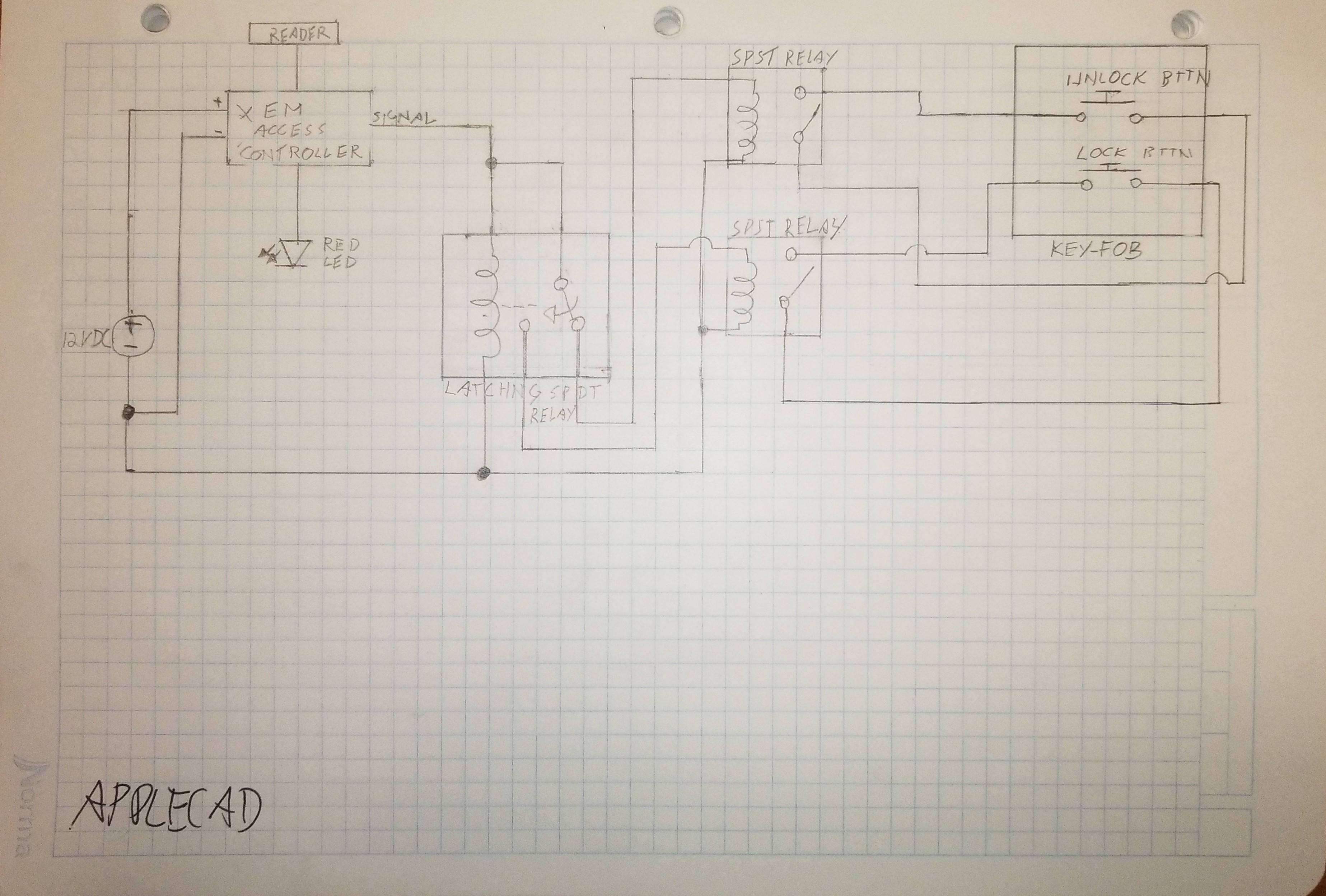
Do you think this would work to switch between “pushing” the locked and unlocked buttons?
I don’t think it would be a problem for the xEM to actuate 2 relays?
All I’m worried is that in this configuration, the latching SPDT relay will power actuate one button before switching and then activating the other one. Maybe that could be an issue?
Maybe something can be done to prevent that?
You wish… The damn thing has an immobilizer that uses a 433 MHz ID46 transponder in the key fob.
I’ll have to remove the ignition key lock tumbler/cylinder and switch (probably get a garage to do that bit, since it takes some heavy drilling), saw off the steering column lock, solder wires to the ignition switch, put everything back together and duct-tape my spare key in front of the antenna inside the steering column.
And even then, I’m not sure it won’t trip the computer: from what I could read, some cars expect the chip to “come into view” of the antenna only when the key is turned. When those computers read the chip with the key in the off position, they disable the engine.
An easier solution would be to leave the key in the car at all times, and simply disable the ignition with the xEM. That’s one way to go keyless with RFID and have a separate ignition switch The trouble with that is, it’s an open invitation for car thieves to break the window in the hope of an easy steal.
Yes that would work, if you looked at switching up the circuit to use transistors and optocoplers you could do it small enough to fit inside the xAC. But in principle nothing wrong with your circuit.
APPLE-CAD Is that freeware? looks pretty well spec’d
.
Circuit diagram looks good to me.
With your Double throw relay ( you probably already thought of it, sorry if I missed it in your diagram ), I would suggest the normally Open is your lock state, so when Unlocked, your car will likely be driven- and alternator charging battery, and when locked, no current draw.
Good question, at first I thought there was no issue, but you made me think
about it…I think I know where you are coming from. I think it will be fine…I think
leave the transponder in the car right by the ignition.( around the ignition barrel )
Lock the car
Wait a period of time
Unlock the car
Start the car ( With the transponder still in place )
If it works, you should be golden!
Obviously I’m not familiar with your car, but the handful I have dealt with, your process sounds more extreme than I would have thought necessary.
Remove the steering boss/shroud
You should find somewhere on the barrel housing a small metal detent
Use a screwdriver or similar to depress the detent at the same time
insert the key and turn it to ACC or on.
The detent should “give” and you will be able to remove the lock barrel.
TA DA
Around your lock barrel shroud you should see the immobiliser antenna, which is where, IF your transponder test from above worked, you will hot glue / tape your transponder in place.
The hole where your key barrel was, Is now where you can mount your Push to start button.
HOPEFULLY, this process makes sense and more importantly it works for YOUR current setup.
If not, let us know how your testing goes, and maybe start your own thread in the projects section, talk us through your findings, and hopefully through the community somebody will be able to help.
So in the diagram I’m planning on powering both the latching spdt relay and the spst relays all 3 with the signal line of the xEM access controller (xEMac) , that way when the xEMac signal line goes low and stops sending 12v+ then all relays are unpowered. Therefore the only device drawing power is the xEMac.
Or should I maybe not drive all relays with the signal line?
No, right you are, Good catch…Relays only energised when your xEM/NExT is presented.
Therefore your only current draw should be your xAC of around 11mA