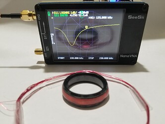
Help designing 125khz passive inductance coil for T5577

I was interested in purchasing the DT Magic Ring but they dont make it in my size. I contacted DT and they informed me the larger sizes dont sell much and they have no intention of making even larger sizes. So, I decided I would try to make my own.

The chip is a T5577 (given for chip, but going to state anyways, frequency 125khz) taken from a melted down card. I was able to read an write to it once removed and using its original antenna. Different cards had slightly different original antennas, even though they all used the T5577 chip. They were all single layer style antennas ranging from:
Coil outer diameter: 43-37mm
Coil Length: 3.5-5mm
Wire diameter: 0.03-0.04mm

The ring I am trying to make has the following data points:
T5577 measured capacitance: 0.175nF
Ring outer diameter (coil inner diameter): 25mm
Ring channel width (coil length): 4mm
Wire gauge for antenna: 32awg or 0.2mm (enameled coated magnet wire)
Inductance: ???
Number of Turns: ???

Extra measurements I took that may be useful (I do not own nor have access to an oscilloscope):
Diode: 2.19V
Ohms reads open line

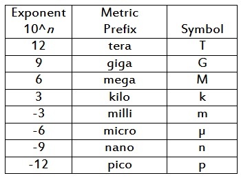
Using the calculator here the calculated Inducatnce (L) given the above data is 0.009263651µH (9.263651nH).
Using this calculator and the above data the Number of Turns is listed as 2, which doesnt sound correct, but more importantly doesnt read.

Through other documentation I found (only have the pdf, cant find link), it looks like the inductance may be between 4.8-5.0mH which equates to 321 turns, which also doesnt sound right and would stack WAY above the ring.

Using yet some other documentation, I found the documented inductance to be 330uH. This led to 90 turns, which is near the limit of the ring channel I have, and I could successfully read and write, though only from about an inch away. I have purchased ring that will read from almost 3 inches, so I think there is still something not quite right.
I played near this 90 turn range from 80 (which didnt read) to 125 (which was a little excessive for the ring size and stopped reading).
The issue here was it would work when I wasnt wearing it but would stop reading when it was on my finger. The commercially produced ring worked on my finger at about 1 inch, so it seems there is a factor about the body I may also be missing.

How can I determine the inductance and/or number of turns needed? I would greatly appreciate if someone could walk me through the calculation.

If this is not sufficient to calculate, could you please also let me know what other data you need?
1 Like

Hey Taggart,

I made a post here in a thread with tons more information about this topic. Feel free to read through that, and respond here about your specific project. You’re doing great so far, but this can become black magic real quick.

2 Likes

Yup, that ferrite sheeting should work. It changes the mu value of the inductance equation in the second post on that thread. Air is a relative permeability near one, whereas those sheets are probably around 300. So it’s going to significantly impact your inductance. It’s difficult to predict without knowing all the properties of the material, that’s why the VNA helps.

A steel ring could work, but if it’s too thick it will impede the flux instead of propagating it. It would also have to be regular steel, not stainless

2 Likes

Thank you @Satur9. This was actually one of the posts I read before, but chose not to post to it because it was specific to 13.56MHz. Also looking back I am now realizing I used MHz instead of KHz in my calculation which threw off the inductance calculation.

Given your explanation and calculated inductance, 66pacific is calling for approximately 127 turns, which is a bit large for what I am working with. I am interested in this ferrite strip as a solution. Does this change any of the calculations? Or does it just enhance the magnetic field to get a longer read distance?
How thin should this be? Would something like this work?
Would a steel ring core work if I magnetized it?

I should also note in my design I am using a ceramic ring core. Based on what I have read appears to have the same or nearly the same permeability as air. I’m assuming my finger is changing this, but from what I have read it is also similar to air.

1 Like

I will give that a try.
I ordered the VNA too. I was having a hard time stomaching $400-500 for an oscilloscope, but $60 for a VNA is reasonable.
Dang, should have asked this before purchasing the ring cores. I went with a stainless thinking I wanted to avoid magnetic interference, so I should select materials that were non-ferris.
Thanks for all your help.

2 Likes

@Satur9 Supplies and VNA are in! I realized I made some huge errors in conversions in some of my pervious posts.
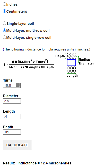
Correcting those conversions in the 66philip calculator gives ~17 turns (actually is 16.8)

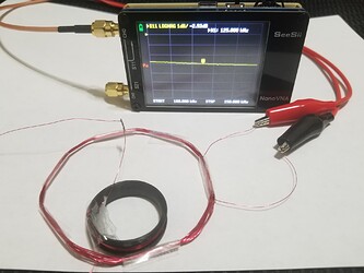
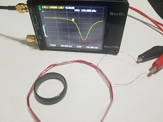
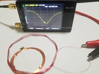
Using a known good antenna, I verified the VNA was setup and reading correctly

Than checked my ring using the calculated 17 turns, Tested up to 20 and down to 14 and in multiple locations around the antenna but didnt see any reading. I tried expanding the range on both sides but still no reading.

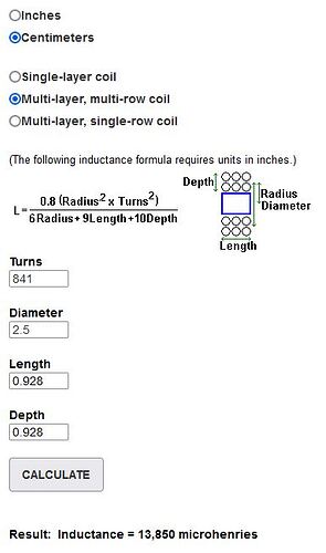
I am trying to calculate the inductance using the ferrite core calculation but I am not sure what the resulting unit is. I started with u = 1 as a baseline to compare to the 12.4mH on the other calculator but I am getting triple the value at 35.4 using the following:
L = (u*(N^2)A)/l
u = 1
N = 17
A = πr^2 from the diameter 25mm = π
(0.025/2)^2 = 0.000491 m
l = 4mm = .004m
L = 35.4 (guessing this is mH???)

I did try wrapping the ferrite core using the same 14-20 turns and it too didnt register on the VNA.

Entering black magic territory. Not sure where to go from here. Thoughts?

17 turns would give you 12.4uH not 12.4mH. Off by a factor of 1000

981921187

Assuming you have 28AWG magnet wire which is 0.32mm thick, and you wind a coil that is 29 turns wide and has 29 layers stacked, you would get this

That’s gonna be a huge pain to get precise though. Rings are not really ideal for this because of their shape. They’re inherently long relative to their diameter, and they have to be made of durable materials which kinda rules soft metals like ferrite out. Check out the second post in that thread I linked to see what factors affect inductance:

or, you could just come to the same conclusion that everyone here has and decide that wearables are dumb and you should just get an implant. Not sayin, just sayin.

1 Like

Damn conversions…

My issue is I know it “can” be done because there are commercial options available. While this one is not tuned great, it still works decently well.

The end of my last post, I tried to calculate the inductance using the formula in your post, but Im not sure what the result actually means nor why it seems so far from another method to calculate what I thought should be the same value.

I mean I definitely recommend you stick with an online calculator, but if you really want to calculate it manually I’ll give it a go.

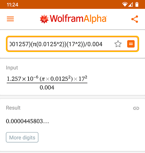
L = (u * N² * A) / l

u = 0.000001257H/m
N = 17
A = 0.000491m²
l = 0.004m

L = 44.6uH

2 Likes

I absolutely would stick to the calculator, but that one just provided a formula.
Thank you for also filling in the unit gap. I was not sure what the result was (H, mH, uH, or other). This is extremely helpful! Thank you VERY much.

2 Likes

Again, many thanks @Satur9. I really couldn’t have done this without your guidance.
It’s terribly tuned, but it works! The next one I will focus on tuning.

One of the biggest issues I had (other than my inability to math) was the wire gauge. I was using 32 gauge, which was too thick. At 100 turns it became level, and even slightly proud, with the top of the ring. One of your comments indicated that the number of turns is more important, so I went with 44 gauge and there’s even extra room after 300 turns.

3 Likes

Glad you got it worked out mate =) the hard part is always the math. Luckily it doesn’t lie

1 Like