True that. I just have this weird tick where something small like this will eat at me until I suddenly have an AHA moment. Guess it’s time to solder shit up and run some cable.
Final code release 0.2.1. I really need to get a github.
Since this is a production release, I removed much of the debug output and only display critical debugging.
Initial search can’t find any documentation on how to use the iclass SE red and green LED wires. Attemping to pull them up and down didn’t seem to do anything. So LED functionality has been removed.
I was planning on running the wire for the first install this weekend. We will see, time permitting.
OTA software updates have been tested and are successful. I am able to remotely update the code/authorizedCards on all devices.
/*
Software reads RFID input from Wiegand reader
Connects to wifi and communicates over MQTT
 08-04-2020 - Intial production release - REB
 */

#include <Wiegand.h>
#include <PubSubClient.h>
#include <ESP8266WiFi.h>
#include <WiFiUdp.h>
#include <ArduinoOTA.h>

// These are the pins connected to the Wiegand D0 and D1 signals.
#define PIN_D0 D5
#define PIN_D1 D6

//Array of authorized card
const char* AuthorizedCards[] = {"4BYTEHEX1","4BYTEHEX2"};
const int numAuth = 2; //when adding a new authorized card, increase this to the number of authorized cards

// WIFI Variables
char ssid[] = "marsellus_wallace";            // your network SSID (name)
char pass[] = "lookslikeabitch";        // your network password
char remoteName[] = "rfid_front_door";


//MQTT server and creds
const char* server = "192.168.1.1";
const char* username = "hacker";
const char* password = "dogs>cats";
const char* UID = "arduino-1";
const char* mqttTopic = "access/rfid/front_door";

// The object that handles the wiegand protocol
Wiegand wiegand;

// Handler for MQTT received messages
void callback(char* topic, byte* payload, unsigned int length) {
  // handle message arrived
}

// Initialize ethernet and mqtt clients
WiFiClient ethClient;
PubSubClient client(server, 1883, callback, ethClient);


boolean reconnect() {
  Serial.println("Reconnecting to MQTT server.");
  if (client.connect(UID, username, password)){
    Serial.println("Connected to MQTT");
  } else {
    Serial.println("Failed to connect to MQTT");
  }
  return client.connected();
}

// Initialize Wiegand reader
void setup() {
  Serial.begin(9600);

  //initialize pins for Wiegand communication
  pinMode(PIN_D0, INPUT);
  pinMode(PIN_D1, INPUT);

  // initialize ESP module
  // Set wifi mode for power saving and connect
  WiFi.mode(WIFI_STA);
  Serial.println("Connecting to WIFI");
  WiFi.hostname(remoteName);
  WiFi.begin(ssid, pass);

  // attempt to connect to WiFi network if connection fails until it connects
  while (WiFi.waitForConnectResult() != WL_CONNECTED) {
    Serial.println("Connection Failed! Rebooting...");
    delay(5000);
    ESP.restart();
  }

  // Print network and IP for debugging purposes
  Serial.print(remoteName);
  Serial.print(" is connected to network ");
  Serial.print(ssid);
  Serial.print(" with IP address ");
  Serial.println(WiFi.localIP());

  //Install listeners and initialize Wiegand reader
  wiegand.onReceive(receivedData, "Card readed: ");
  wiegand.onReceiveError(receivedDataError, "Card read error: ");
  wiegand.onStateChange(stateChanged, "State changed: ");
  wiegand.begin(Wiegand::LENGTH_ANY, false);

  // Connect to MQTT
  reconnect();

  // Code for OTA flashing
  ArduinoOTA.onStart([]() {
    String type;
    if (ArduinoOTA.getCommand() == U_FLASH) {
      type = "sketch";
    } else { // U_FS
      type = "filesystem";
    }

    // NOTE: if updating FS this would be the place to unmount FS using FS.end()
    Serial.println("Start updating " + type);
  });
  ArduinoOTA.onEnd([]() {
    Serial.println("\nEnd");
  });
  ArduinoOTA.onProgress([](unsigned int progress, unsigned int total) {
    Serial.printf("Progress: %u%%\r", (progress / (total / 100)));
  });
  ArduinoOTA.onError([](ota_error_t error) {
    Serial.printf("Error[%u]: ", error);
    if (error == OTA_AUTH_ERROR) {
      Serial.println("Auth Failed");
    } else if (error == OTA_BEGIN_ERROR) {
      Serial.println("Begin Failed");
    } else if (error == OTA_CONNECT_ERROR) {
      Serial.println("Connect Failed");
    } else if (error == OTA_RECEIVE_ERROR) {
      Serial.println("Receive Failed");
    } else if (error == OTA_END_ERROR) {
      Serial.println("End Failed");
    }
  });
  ArduinoOTA.begin();
}

// Continuously checks for pending messages and polls updates from the wiegand inputs
void loop() {
  // Checks for pending messages
  wiegand.flush();

  // Check for changes on the the wiegand input pins
  wiegand.setPin0State(digitalRead(PIN_D0));
  wiegand.setPin1State(digitalRead(PIN_D1));

  // Handle OTA flashing if detected
  ArduinoOTA.handle();
}

// Notifies when a reader has been connected or disconnected.
// Instead of a message, the seconds parameter can be anything you want -- Whatever you specify on `wiegand.onStateChange()`
void stateChanged(bool plugged, const char* message) {
    Serial.print(message);
    Serial.println(plugged ? "CONNECTED" : "DISCONNECTED");
}

// Notifies when a card was read.
// Instead of a message, the seconds parameter can be anything you want -- Whatever you specify on `wiegand.onReceive()`
void receivedData(uint8_t* data, uint8_t bits, const char* message) {
    String CardCode = "";
    //Print value in HEX
    uint8_t bytes = (bits+7)/8;
    // iclass SE is reporting the UID backwards, so this loop starts at the end of the array and walks back
    for (int i=bytes-1; i>=0; i--) {
      // Copy HEX to variable CardCode
      String FirstNum = (String (data[i] >> 4, 16));
      String SecondNum = (String (data[i] & 0xF, 16));
      CardCode = (CardCode + FirstNum + SecondNum);
    }

    // Call authentication function with scanned card
    authenticateCard(CardCode);
}

void authenticateCard(String CardHex) {
  // Loop through authorized cards to see if scanned card is authorized
  for (int i=0;i<numAuth;i++){
    if ( CardHex == AuthorizedCards[i] ) {
      // Card is authorized
      // Reconnect to MQTT server if connection dropped
      if (!client.connected()) {
        Serial.println("MQTT not connected.");
        if (!reconnect()){
          // Set LED to RED and error for debugging
          Serial.println("Unable to connect to MQTT");
        }
      }

      // Publish unlock message to MQTT broker
      client.publish(mqttTopic, "unlock");

      // Exit loop
      i=999;
    }
  }
}

// Notifies when an invalid transmission is detected
void receivedDataError(Wiegand::DataError error, uint8_t* rawData, uint8_t rawBits, const char* message) {
    Serial.print(message);
    Serial.print(Wiegand::DataErrorStr(error));
    Serial.print(" - Raw data: ");
    Serial.print(rawBits);
    Serial.print("bits / ");

    //Print value in HEX
    uint8_t bytes = (rawBits+7)/8;
    for (int i=0; i<bytes; i++) {
        Serial.print(rawData[i] >> 4, 16);
        Serial.print(rawData[i] & 0xF, 16);
    }
    Serial.println();
}
1 Like
Quick update from HID. iclass readers come default 32 bit MSB. Mifare cards use LSB, which is why the UID is backwards. For the 7byte UID on a Mifare, the readers needs to be 56bit LSB.
Inquiring if a configuration card will resolve the issue. Otherwise, it’s not anywhere near enough of an issue to purchase new readers.
1 Like
Well, I got SOME help from HID. Told me to order config card SEC9X-CRD-0-005J from a HID reseller. It will do exactly what I want it to do. Price seems to be around $30. Was kind of hoping HID would be nice enough to offer the card, but I guess not since I’m not an authorized customer. I wonder if I found someone with the card, if I could clone it. I don’t think the problem is big enough to spend $30 to fix it.
Just a heads up @cexshun and for anyone duplicating this project. Wiegand data lines run at 5V, but the Wemos D1 Mini is a 3.3V device that does not have 5V compliant input pins. While it might operate for now, a couple days/weeks down the line you could fry the input pins the reader is hooked up to. If you wanted a longer lifespan, I would recommend a logic level converter, or at the very least a 1K ohm resistor in series with each input and a 3.3V Zener diode in parallel running to ground (stripe towards pin)
2 Likes
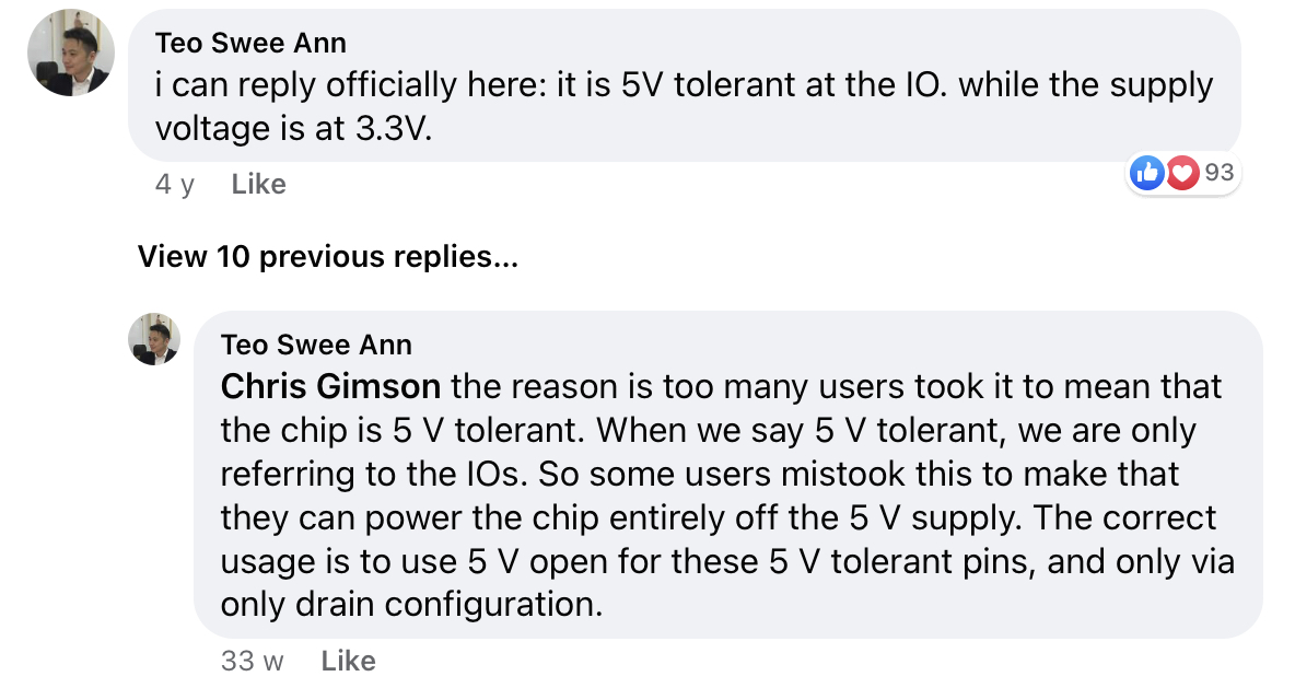
You’re correct according to the datasheet, but the data lines are actually 5v tolerant, as long as the rail voltage is 3.3. If you scroll down at this link you’ll see a comment from the CEO of Expressif. I’ve never fried one operating with Wiegand or any 5V data for that matter.
I found the same information that @Compgeek found. But I supposed I should grab a handful of Sparkfun logic level converters to be safe. Looking at the converter schematics, it looks to be a BSS138 N channel mosfet and 2 resistors per channel.
Edit; With all of the knockoffs and knockoff of a knockoff flying around the random China companies on Amazon, it’s certainly safer to use a logic converter as one never know exactly what they are getting. I just ordered 5 Sparkfun converters from Digikey in order to make the $5 shipping worth it. Cost me $20.
1 Like
Well, during the install. everything went to shit today. Ran the shielded cable, got everything soldered up and programmed. But the reader is only giving my 50%-70% read accuracy. Using a test card with ID BEAF76C1, here’s my results if I do 20 consecutive reads.
beaf76c1 was read. Correct
be57bb60 was read. Incorrect
beafbe60 was read. Incorrect
be5fbb60 was read. Incorrect
beaf76c1 was read. Correct
de57bb60 was read. Incorrect
beaf76c1 was read. Correct
beaf76c1 was read. Correct
beaf76c1 was read. Correct
beaf76c1 was read. Correct
beaf76c1 was read. Correct
be57bb60 was read. Incorrect
beaf7661 was read. Incorrect
beaf76c1 was read. Correct
be2f5b30 was read. Incorrect
beaf76c1 was read. Correct
be5fbb60 was read. Incorrect
beaf76c1 was read. Correct
beaf76c1 was read. Correct
beaf76c1 was read. Correct
This round of testing was 12/20 correct. This is nowhere near close enough to be used. Some tests I’ll get up to 14/20, and some tests 10/20.
Anyone have any thoughts? I’ve tried connecting the drain wire to ground and to earth, neither fixed the problem. Cable run is roughly 20ft, give or take, using 22awg shielded cable using 4 of the 8 conductors.
Swapped out readers, same problem. Moved reader directly connected to the Wemos with no cable, still have issues.
be57bb60 was read. Incorrect
beaf76c1 was read.
beaf76c1 was read.
beaf76c1 was read.
beaf7641 was read. Incorrect
beaf76c1 was read.
beaf76c1 was read.
beaf76c1 was read.
be57bb60 was read. Incorrect
beaf76c1 was read.
beaf76c1 was read.
beaf7661 was read. Incorrect
beaf76c1 was read.
be57bb60 was read. Incorrect
beaf76c1 was read.
beaf76c1 was read.
beaf76c1 was read.
beaf76c1 was read.
beaf76c1 was read.
beaf76c1 was read.
15/20
Found the problem. I yanked everything out except the reader and the Wemos. Loaded a sketch that does nothing but read the Wiegand data and dump it to the screen. It still was averaging 60% accuracy.
I even hooked up the AWID scanner that I know is good. Same results.
So I hooked up the reader to the old Arduino Duemilanove. Son of a bitch reported 100% accuracy.
So the problem seems to be with the Wemos D1 Mini. I have 0 clue wtf is going on…
I’ve been able to improve accuracy by adding a 1.6kohm pullup resistor. Still getting 80% accuracy, which in my opinion isn’t adequate for a door lock.
Put in an order for a “name brand” Wemos board and an Arduino 33 IoT. Going to play with those 2 boards and see if the issue resolves. The old Arduino still getting 100% accuracy with the same code and wiring, and even without pull up resistors.
This one from addicore has always served me well for my projects. Never used it with wiegand, just I/O to a motor driver board. I usually use a raspberry pi with with series current limit resistors and parallel 3.3V zeners on the input lines for my wiegand projects.
The Duemilanove operates at 5V, just like the wiegand readers. Just sayin
The logic level shifters will be here soon. I suppose there’s a chance that the 5v Wiegand signal is screwing with the Wemos. We’ll see. Can never have too many Arduino style devices. I grabbed the Wemos from MakerFocus. $8 for 1 vs the 5 for $15 I ordered last time.
1 Like
Logic level converter hooked up. Voltages reading fine. Pulled the data lines up to 3.3v. Still getting bad reads.
Card readed: 32bits / C176AFBE
Card readed: 32bits / C176AFBE
Card readed: 32bits / C176AFBE
Card readed: 32bits / C176AFBE
Card readed: 31bits / 4176AFBE
Card readed: 32bits / C176AFBE
Card readed: 32bits / C176AFBE
Card readed: 32bits / C176AFBE
Card readed: 32bits / C176AFBE
Card readed: 32bits / C176AFBE
Card readed: 32bits / C176AFBE
Card readed: 31bits / 60F6AFBE
Card readed: 32bits / C176AFBE
Card readed: 32bits / C176AFBE
Card readed: 32bits / C176AFBE
Card readed: 32bits / C176AFBE
Card readed: 32bits / C176AFBE
Card readed: 32bits / C176AFBE
Card readed: 32bits / C176AFBE
Card readed: 32bits / C176AFBE
Card readed: 32bits / C176AFBE
Card readed: 32bits / C176AFBE
Card readed: 32bits / C176AFBE
Card readed: 32bits / C176AFBE
Card readed: 32bits / C176AFBE
Card readed: 32bits / C176AFBE
Card readed: 32bits / C176AFBE
Card readed: 32bits / C176AFBE
Card readed: 32bits / C176AFBE
Card readed: 31bits / 60BB5FBE
Card readed: 32bits / C176AFBE
Card readed: 32bits / C176AFBE
Card readed: 31bits / 60BB57BE
Card readed: 31bits / 60BAAFBE
Card readed: 32bits / C176AFBE
Do you happen to have an oscilloscope? It definitely sounds like noise. Maybe from the power supply. Do the reader and Wemo share power? What about a smoothing cap on the power line? The Wemo may be putting noise on the power line which messes with the reader. That could be noise on the RF side causing data errors on the read or noise on the data lines themselves going to the Wemo.
I have a cheap pocket oscilloscope, DSO Nano v3. Never used it for anything besides tuning an amplifier.
Reader is getting power off of the 12v wall wart. Wall wart goes through an adjustable buck converter (based on XL4015) that drops it to 5v that goes into the Wemos. Everything running off of a common ground.
Data lines come from the reader directly to a logic converter getting 5v off of the same 5v going into the Wemos, and 3.3v coming off of the Wemos 3.3v pin. Voltage on each side seems fine. Data lines are pulled up to the same 3.3v rail with 1.6kohm resistors to eliminate floating.
Edit: Buck converters are https://smile.amazon.com/gp/product/B079N9BFZC/
those buck converters seem like overkill and also seem … noisy… why not a simple 5v regulator;
They are overkill. I picked them up as they are much more versatile than the other regulator, and since everything comes in multipacks, I’ll have more uses for the left over units. The circuit is pretty exact to the spec sheet of the XL4015, except the output cap is 220uF while the spec sheet suggests 330. Not sure why it would be noisy though.
Standard buck converters use switching tricks, switching invariably introduces some noise… but usually it can be filtered properly with capacitors… but sometimes not… and sometimes it sets up just the wrong kind of resonance on the line that turns a tiny bit of noise into a huge problem.
Probably helpful to add that the issue occurs when just using USB power also. Under powers the reader and very difficult to get an implant to read, but will still read the test card I’m using. Same errors occur.