Home Assistant integrated HID iclass SE

Started this project last night. All of the parts have arrived except for the iclass readers which haven’t shipped yet.

First off, huge props to Compgeek for turning me on to the Wemos D1 Mini. This project will be based on that board. Super small, low power draw, and more power than I’ll ever need for this project.

I chose to go with the iclass SE because my xEM is flashed often for various purposes. However, the xNT UID always stays the same. So basing my scanners on 13.56. My previous AWID project was more a research project that an actual use case.

The code from the previous project was very easy to change for the Wemos D1 board. The biggest changes were using the correct 8266WiFi.h file, and I had a few competing files of the same name. Also, the pins are referred to in a different number scheme, so I had to convert the INPUT/OUTPUT pins to use the Wemos constants of D2 and D3 instead of 2 and 3. And a few tiny changes like the way functions return values.

Parts list:
Wemos D1 Mini
12v 1amp wall wort
Adjustable step down buck driver
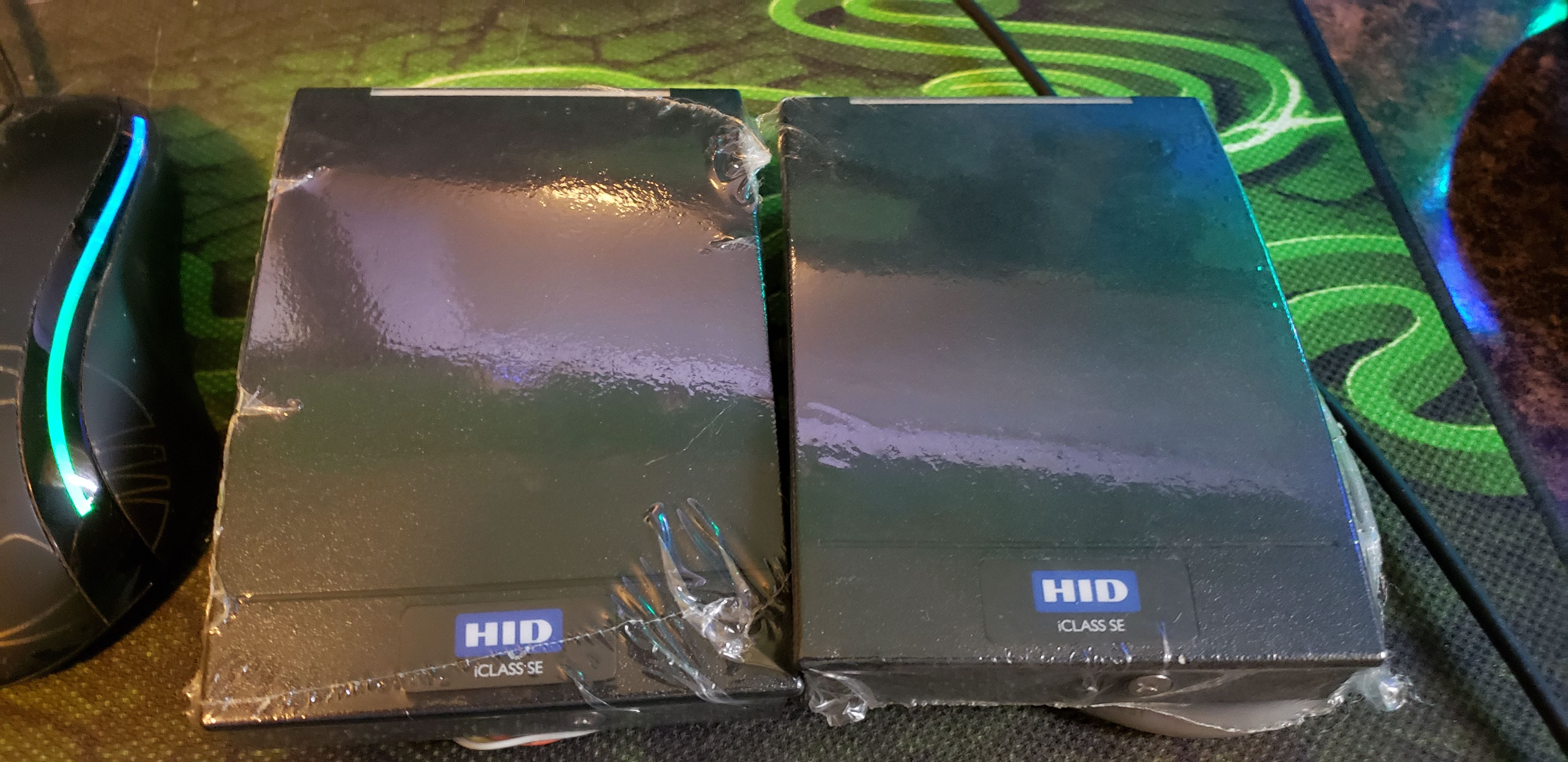
Used HID iclass SE(NOT THE MULTICLASS)
22AWG 8 conductor shielded cable

Many products were purchased in multi packs, so the price breakdown per unit is $33 not counting the cable as the price differs greatly based on length needed. $22 of that going to the used iclass SE.

There are a wide variety of Chinesium 14443a compliant scanners. However, in addition to reviews stating poor range, the cables are not shielded and there isn’t even a shield wire. So I paid the few dollars more(literally $4 more) for the used iclass SE.

The readers will have the best range with the higher voltages. So the reader will be powered off the full 12v from the wall wart, and the Wemos will be powered off the adjustable buck driver. I spent more on the adjustable buck drivers because it’s a multipack, and the left over units are much more useful with the wider range of input and output voltages, and they are more efficient. Could have saved a few dollars going with the cheap 12v to 5v linear buck converters.

The readers will be placed outside at the 2 doors. My house was built in 1958, so there is only 1 outdoor electrical outlet. But I do have a basement with direct access to the 2 locations. So the Wemos will be in the basement, and the shielded cable will be ran out to the readers. Since the cable runs will be roughly 10ft, I feel a lot more confident using shielded cable.

Much like my previous AWID project, this project connects to my IoT wifi network and passes MQTT messages to Home Assistant. The biggest change to this project is that the Wemos are programmable over the network. So I added the code to allow for network flashing for ease of upgrades. With the new Wemos boards, I’m already experiencing massive performance gains. With the aged Duemilanove, it took about 15 seconds to boot, connect to wifi, then connect to MQTT. This new board does the same in 2 seconds.

Hopefully, the next post will be a success with a demo as I believe all I have to do is swap out the AWID reader for the iclass reader. But if not, it will be more of a build log.

5 Likes

Great stuff!

Glad you’re loving the D1 and it’s performing well for you, and also a great write up,

Would you consider sharing your arduino sketch? I’m not sure how many people will find it applicable to their needs, but would be a great reference.

1 Like

Sure thing. Let me add some code comments and edit out personal information.

The 1 catch with the code is that it stores UIDs hardcoded, which isn’t a big deal with network flashing, but I’d really love to eventually work out EEPROM storage.

1 Like

Here’s my code. Keep in mind I’m a Linux Sysadmin, recently converted to SRE. So coding is well outside my area of expertise. Advise and constructive criticism is always welcome! The follwing libraries are needed:
YetAnotherWiegandLibrary (I’m using polling, but it also supports interrupts)
PubSubClient (MQTT)
Official Arduino Wemos libraries

#include <Wiegand.h>
#include <PubSubClient.h>
#include <ESP8266WiFi.h>
#include <WiFiUdp.h>
#include <ArduinoOTA.h>

// These are the pins connected to the Wiegand D0 and D1 signals.
#define PIN_D0 D2
#define PIN_D1 D3

// LED pin to pull change LED color
#define PIN_LED D8

//Array of authorized card
const char* AuthorizedCards[] = {"HEXUID1","HEXUID2"};

// WIFI Variables
char ssid[] = "starbucks";            // your network SSID (name)
char pass[] = "hahaha_not_startbucks";        // your network password


//MQTT server and creds
const char* server = "192.168.1.1";
const char* username = "users";
const char* password = "password";
const char* UID = "iclass-se-1";
const char* mqttTopic = "acces/rf/front_door";

// The object that handles the wiegand protocol
Wiegand wiegand;

// Handler for MQTT received messages
void callback(char* topic, byte* payload, unsigned int length) {
  // handle message arrived
}

// Initialize ethernet and mqtt clients
WiFiClient ethClient;
PubSubClient client(server, 1883, callback, ethClient);


boolean reconnect() {
  Serial.println("Reconnecting to MQTT server.");
  if (client.connect(UID, username, password)){
    Serial.println("Connected to MQTT");
  } else {
    Serial.println("Failed to connect to MQTT");
  }
  return client.connected();
}

// Initialize Wiegand reader
void setup() {
  Serial.begin(115200);
  
  //initialize pins for Wiegand communication and LED control
  pinMode(PIN_D0, INPUT);
  pinMode(PIN_D1, INPUT);
  pinMode(PIN_LED, OUTPUT);

  // initialize ESP module
  // Change LED to RED to show reader is not ready
  digitalWrite(PIN_LED,HIGH);

  // Set wifi mode for power saving and connect
  WiFi.mode(WIFI_STA);
  Serial.println("Connecting to WIFI");
  WiFi.begin(ssid, pass);
  
  // attempt to connect to WiFi network if connection fails until it connects
  while (WiFi.waitForConnectResult() != WL_CONNECTED) {
    Serial.println("Connection Failed! Rebooting...");
    delay(5000);
    ESP.restart();
  }

  // Print network and IP for debugging purposes
  Serial.print("You're connected to the network ");
  Serial.print(ssid);
  Serial.print(" with IP address ");
  Serial.println(WiFi.localIP());

  //Install listeners and initialize Wiegand reader
  wiegand.onReceive(receivedData, "Card readed: ");
  wiegand.onReceiveError(receivedDataError, "Card read error: ");
  wiegand.onStateChange(stateChanged, "State changed: ");
  wiegand.begin(Wiegand::LENGTH_ANY, false);

  // Connect to MQTT
  reconnect();

  // Set LED to GREEN as we're in a good state
  digitalWrite(PIN_LED,LOW);

  // Code for OTA flashing
  ArduinoOTA.onStart([]() {
    String type;
    if (ArduinoOTA.getCommand() == U_FLASH) {
      type = "sketch";
    } else { // U_FS
      type = "filesystem";
    }

    // NOTE: if updating FS this would be the place to unmount FS using FS.end()
    Serial.println("Start updating " + type);
  });
  ArduinoOTA.onEnd([]() {
    Serial.println("\nEnd");
  });
  ArduinoOTA.onProgress([](unsigned int progress, unsigned int total) {
    Serial.printf("Progress: %u%%\r", (progress / (total / 100)));
  });
  ArduinoOTA.onError([](ota_error_t error) {
    Serial.printf("Error[%u]: ", error);
    if (error == OTA_AUTH_ERROR) {
      Serial.println("Auth Failed");
    } else if (error == OTA_BEGIN_ERROR) {
      Serial.println("Begin Failed");
    } else if (error == OTA_CONNECT_ERROR) {
      Serial.println("Connect Failed");
    } else if (error == OTA_RECEIVE_ERROR) {
      Serial.println("Receive Failed");
    } else if (error == OTA_END_ERROR) {
      Serial.println("End Failed");
    }
  });
  ArduinoOTA.begin();
}

// Continuously checks for pending messages and polls updates from the wiegand inputs
void loop() {
  // Checks for pending messages
  wiegand.flush();

  // Check for changes on the the wiegand input pins
  wiegand.setPin0State(digitalRead(PIN_D0));
  wiegand.setPin1State(digitalRead(PIN_D1));

  // Handle OTA flashing if detected
  ArduinoOTA.handle();
}

// Notifies when a reader has been connected or disconnected.
// Instead of a message, the seconds parameter can be anything you want -- Whatever you specify on `wiegand.onStateChange()`
void stateChanged(bool plugged, const char* message) {
    Serial.print(message);
    Serial.println(plugged ? "CONNECTED" : "DISCONNECTED");
    if (!plugged){
      digitalWrite(PIN_LED,HIGH);
    }
    else {
      digitalWrite(PIN_LED,LOW);
    }
}

// Notifies when a card was read.
// Instead of a message, the seconds parameter can be anything you want -- Whatever you specify on `wiegand.onReceive()`
void receivedData(uint8_t* data, uint8_t bits, const char* message) {
    String CardCode = "";
    //Print value in HEX
    uint8_t bytes = (bits+7)/8;
    for (int i=0; i<bytes; i++) {
      // Copy HEX to variable CardCode
      String FirstNum = (String (data[i] >> 4, 16));
      String SecondNum = (String (data[i] & 0xF, 16));
      CardCode = (CardCode + FirstNum + SecondNum);
    }

    // Call authentication function with scanned card
    authenticateCard(CardCode);
}

void authenticateCard(String CardHex) {
  // Loop through authorized cards to see if scanned card is authorized
  for (int i=0;i<2;i++){

    //char CardHexArray[9];
    
    if ( CardHex == AuthorizedCards[i] ) {
      // Card is authorized
      Serial.print(AuthorizedCards[i]);
      Serial.println(" is authorized.");

      // Reconnect to MQTT server if connection dropped
      if (!client.connected()) {
        Serial.println("MQTT not connected.");
        if (!reconnect()){
          // Set LED to RED and error for debugging
          digitalWrite(PIN_LED,HIGH);
          Serial.println("Unable to connect to MQTT");
        }
      }

      // Publish unlock message to MQTT broker
      client.publish(mqttTopic, "unlock");

      // Exit for loop
      i=999;
    }
  }
}

// Notifies when an invalid transmission is detected
void receivedDataError(Wiegand::DataError error, uint8_t* rawData, uint8_t rawBits, const char* message) {
    Serial.print(message);
    Serial.print(Wiegand::DataErrorStr(error));
    Serial.print(" - Raw data: ");
    Serial.print(rawBits);
    Serial.print("bits / ");

    //Print value in HEX
    uint8_t bytes = (rawBits+7)/8;
    for (int i=0; i<bytes; i++) {
        Serial.print(rawData[i] >> 4, 16);
        Serial.print(rawData[i] & 0xF, 16);
    }
    Serial.println();
}
2 Likes

The official PUbSubClient has a call to client.loop(); in the Loop function. This keeps the connection alive and checks for new messages that are subscribed to.

However, this function was locking out the wiegand listener. AND it hammered the MQTT broker with traffic. Official documentation says to add a sleep function in Loop. This doesn’t work as I need to constantly monitor the Wiegand listener. Since this device does not subscribe to any messages from the broker, nor is the connection required to stay open, I removed the call to client.loop and simply reconnect when a message needs to be published. Side effects are that it introduces about 50ms delay if the connection to MQTT has dropped. I can live with that.

Also, this Wiegand library strips parity bits, so the HEX UIDs coming in were not matching what Proxmark was showingme. Setting false in
wiegand.begin(Wiegand::LENGTH_ANY, false);
Stops the stripping of parity bits. I do not know if this is necessary with the iclass SE, but will find out when they arrive. It certainly was necessary with the AWID/PROX reader.

I spent some time trying to figure out how to use a for loop to loop through the number of values in the authorizedcards array. Count didn’t work, sizeof didn’t work. Eventually I just hard coded i<2 as I know exactly how many values are in the array. Never did find a way in Arduino code to count the number of values in the array of char arrays.

1 Like

Thanks! Very clean and well commented, and I love the inclusion of serial debugging.

Love the wifi name and password you used haha

1 Like

Awesome! If you get a chance to show a hardware demo with wiring that would be great info too.

I will as soon as the 13.56 readers arrive. If you’d like, here’s a video of my other project using a 125 reader. This project is more a less an upgrade of that project. More details and wiring schematics will be included in this build log when the final parts arrive.

Look what arrived today.

1 Like

Here’s the wiring drawing. A little sloppy as I’ve never used Fritzing before.

Wall wart is supplying 12v to the bottom rail. Buck converter drops it to 5v and powers the top rail.

The iclass SE reader, represented by the generic sparkfun mifare reader, is powered off of the 12v rail. Output 0 goes to digital pin 2 on the Wemos. Output 1 goes to digital pin 3 on the Wemos. Digital pin 8 goes to the LED wire on the reader, and I don’t think there is one represented on the model. It’s not necessary anyway.

Wemos is powered off of the 5v rail.

Wires up MUCH cleaner than using an Arduino + 8266 + voltage dividers.

Great stuff! One more ‘this is a product’ suggestion, you can get a ‘power shield’ for the D1 - not any better than what you’re using, but it is the same footprint as the D1 and stacks nicely, and they also have a relay shield for if you did decide to drive an output directly.

Appreciate it. This will be 100% hard soldered. Breadboard just for prototyping and to help electronics noobs. I have a few relays, but no use for them yet as it’s easier to control from Home Assistant.

Having it work now, sort of. Ran into a few problems. For some reason, D2 and D3 just would not pick up the Wiegand data signals. Switching them over to D5 and D6 fixed that and wasted a frustrating amount of time.

And now the bigger problem, the data being read does not match what’s on the chip. Here’s a random magic 1k fob I have lying around according to taginfo:

UID 1A:5F:8A:96

But the Wiegand library is reversing it while keeping the HEX character in the proper order and giving me the following output:

968a5f1a

Trying a fob with a 7bit UID

04:1C:A0:3A:4C:68:80

gives me the following:

1d501c04

Going to take a lot of hammering unless someone has Wiegand coding experience.

Is it the wiegand library doing that, or the reader reporting it in a non-standard format? I think some of the HID readers can be configured in weird modes

Unsure. I just swapped in the AWID reader and got the proper reading.

Since the AWID reader is reading AWID 4bit UID perfectly and Prox 7bit UID perfectly, I have to assume it’s a configuration problem with the iClass SE. However, HID won’t talk to someone that’s not an authorized end user, and I can’t begin to guess what special configuration cards I need to undo this, or how much such cards will cost. I think my only recourse is to code for the reader. Not sure what would be better, using LF and a 7bit UID or using HF and a 4bit UID. I do know the HF has really shitty range.

I reversed the FOR loop that populated the card string. Still only get 4 bytes, but they are in the right order now.

Change this
for (int i=0; i<bytes; i++) {
To this
for (int i=bytes-1; i>=0; i--) {
So now the card string is populated by reading in the array backwards.

Now if I can figure out why it’s only sending 4 bytes.

Alright, so I used the basic example sketch that gives a bit length and UID. The output for all cards says 32bit and reads the 4byte UID backwards.

According to HID:

When reading ISO 14443A cards
(MIFARE®/ DESFire®), the reader can
be configured to output 26-bit, 32-bit
(MSB), 32-bit (LSB), 34-bit, 40-bit or
56-bit Wiegand formats based on the
CSN (card serial number).

Is that was I need to change in order to get a 7byte UID?

Yeah, the reader is in the wrong bit mode. If you want to use a full 7 byte UID, you’ll need to put it in 56 bit.

But your workaround is also fine, as much as 4 bytes is ‘less secure’, it should be secure enough for a domestic use, and as you know, if someone is copying your card anyway and extra 3 bytes is pretty trivial.

I already told my son if he can manage to clone my UID onto a device without me knowing it, then he deserves it.

Looking at the wiegand library I’m using, it supports 26bit and 32bit. Perhaps the reader is sending 56bit and the library just doesn’t support it. Further research is required. Or maybe I’m just reading the docs wrong.

I’d probably just call it a day now you’ve reversed the bits. Getting in to reconfigure HID readers when you’re not a partner as you indicated is really difficult. And 26 bit Wiegand is used to secure government buildings! I think with 32 bit you’re fine for most threats, if they want to get in they’ll smash a window.

Unless you’re going to proper crypto or some sort of rolling code, i think thats good enough.