Hi, I am new to this but learning quickly, I have a project of reducing the antenna size from a standard card to a small size so it can fit on a keyfob.
I have cards I can sacrifice I want to start the project on, but my first question is how do I identify the chip model for I can look up the datasheet? TagInfo is giving me unknown. Is there a database for common bank cards or is there a better tool?
I can measure the antenna inductance with a LCR meter, but how to I find chip capacitance?
Is there anything else I need to be aware of?
Looking to share all the information with the forum incase it comes in handy with anyone doing something similar or just matching a chip to the correct antenna.
Appreciate the help, I’m a total newbie so any guidance would be incredible.
If you have spare ones maybe try and melt one in acetone to retrieve the chip and antenna. A visual inspection of the chip might give you some clues.
Also what bank?
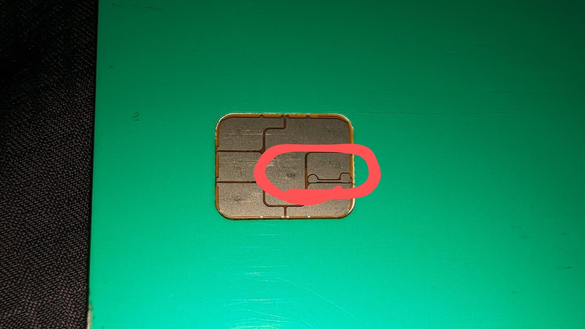
Isn’t there a way to look at the contacts on the chip to tell if it’s possible for a potential conversion? Like if there’s 2 certain contact points you might be able to connect an antenna to those? Or am I mistaken?
I am looking to do this to my entire wallet in the end, but I am starting with Natwest UK and then Amex UK.
UK chips looks visually the same, but I know there can be differences.
I can totally melt the card and extract the chip and antenna, but I am pretty new when it comes to measuring what I need to design a smaller antenna that works with the chips in question.
Antenna (inductor) inductance, chip (capacitor) capacitance and resonant frequency (NFC) are linked. It’s called an LC circuit LC circuit - Wikipedia
You can easily get one parameter from the other two
Hey, I can help. For background you can check out this thread where I’ve compiled background info about making antennas. After this chat I’ll probably add a post explaining how to make repeater antennas for CoM modules.
If you plan to use the chips that are not a CoM module, it’s going to be difficult to solder a new antenna on directly. The problem is that a chip with a contact+contactless interface is usually a bare silicon die with a gold wire bonds connecting it to the contacts. That whole fragile assembly is then coated in a resin to protect it, and that usually makes it hard to access the antenna contacts to solder a new antenna on. You could cut the antenna wire near the chip but outside the resin, and carefully solder (splice) a new antenna you made onto it. I doubt it will work because it’s so fragile though.
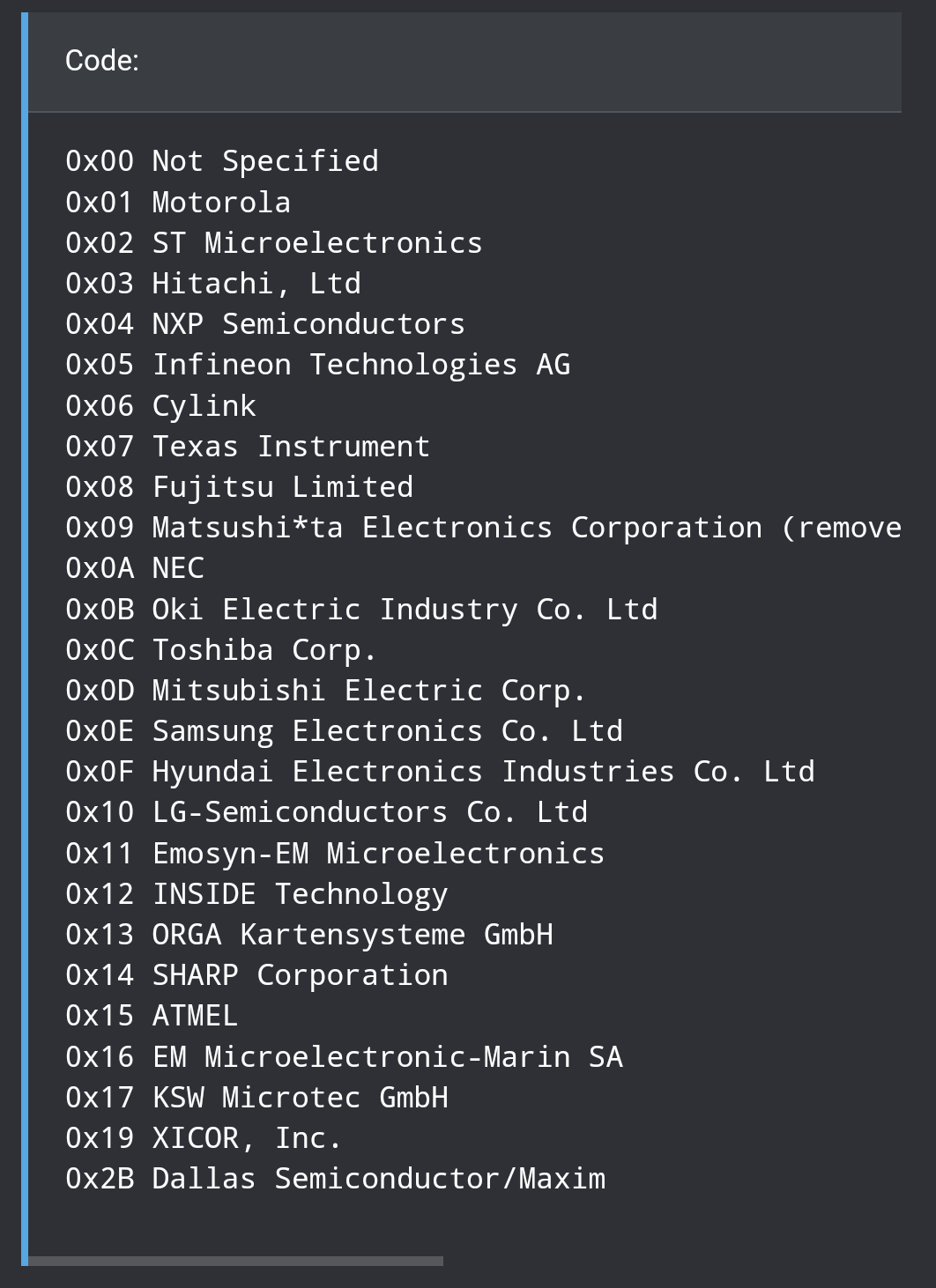
For identifying chips, the first step is to identify the manufacturer. Because of the ISO-14443a spec, any chip must identify itself with a UID when scanned. The first byte of the UID is the manufacturer code. Here’s a list:
Ultimately it doesn’t matter what type of chip it is, because you’re just going to present it to a reader and hope it works. You can’t reprogram payment chips.
If you plan to use the CoM module, you won’t be attaching an antenna directly to the chip, because it already has one. What you’ll be doing is making a completely separate piece that has a larger coil antenna and a capacitor to make it’s own self contained resonant circuit. We’ll call it a resonant repeater. When you place an appropriately tuned resonant repeater up against the CoM module (electrically separate but physically touching), it will shape and direct the field from the reader into the tiny antenna on the CoM module.
If that’s the path you choose, and you want more detailed information about how to do it, let me know and I’ll make a post about it in that thread and ping you.
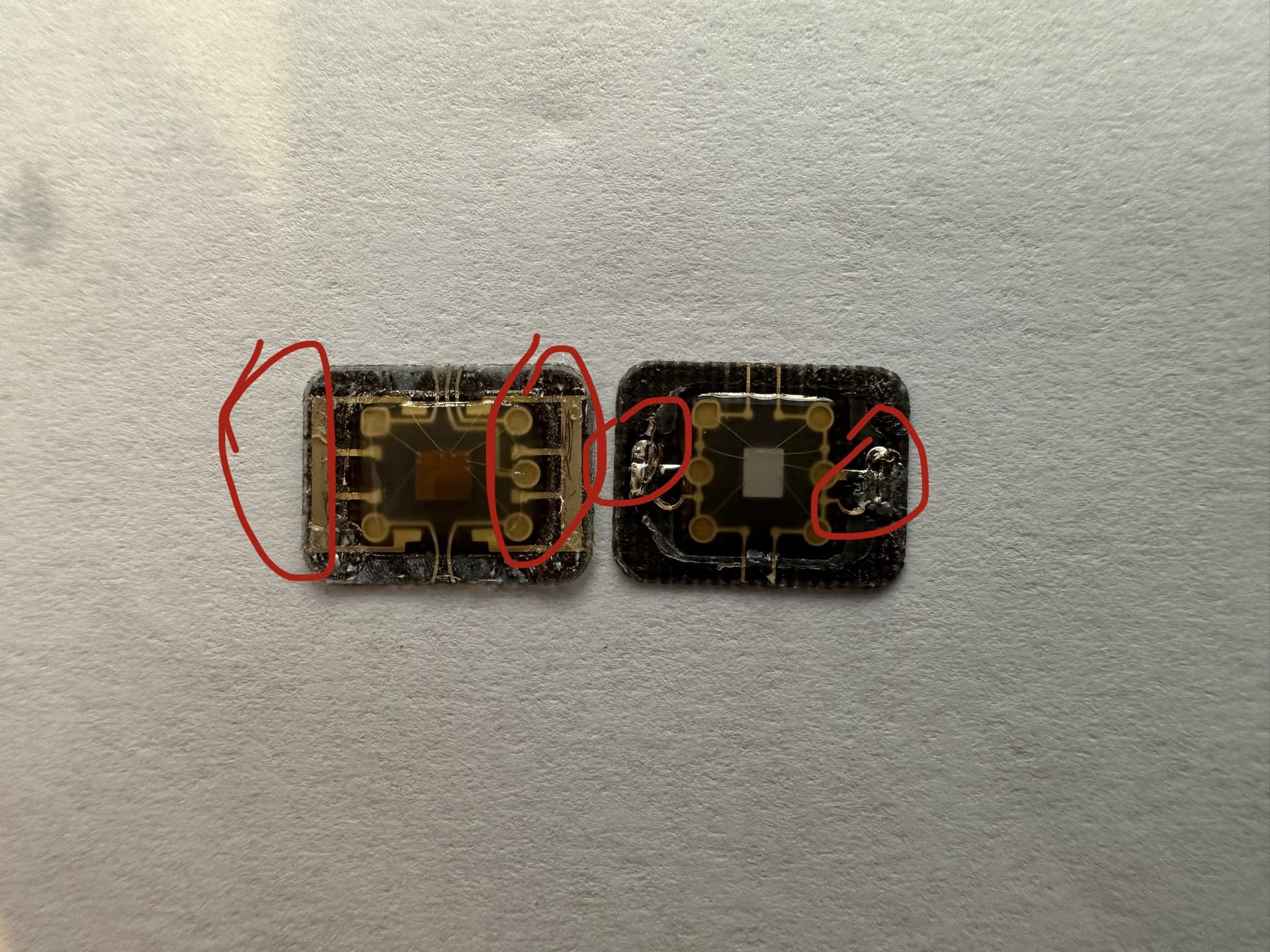
Thanks so much for the information. I have taken a look and I have a mix of chips. I have a picture of a couple here form old cards and a CoM chip. Ill probably make this a project to build my understanding.
Where I have circled is where the original antenna was fixed so my theory was that I could just solder a new new one, or I could get a PCB made up with some sort of semi liquid solder to bridge the connection and just glue the rest of the chip.
If those are in fact connected to the antenna pads on the chip (LA & LB) then you should be able to solder a new antenna on. You can even use an LCR meter or some better multimeters to measure the capacitance of the chip directly. Just make sure you calibrate a zero point with your intended measurement leads first. I would recommend soldering wires directly to ensure it works as expected before making a PCB.
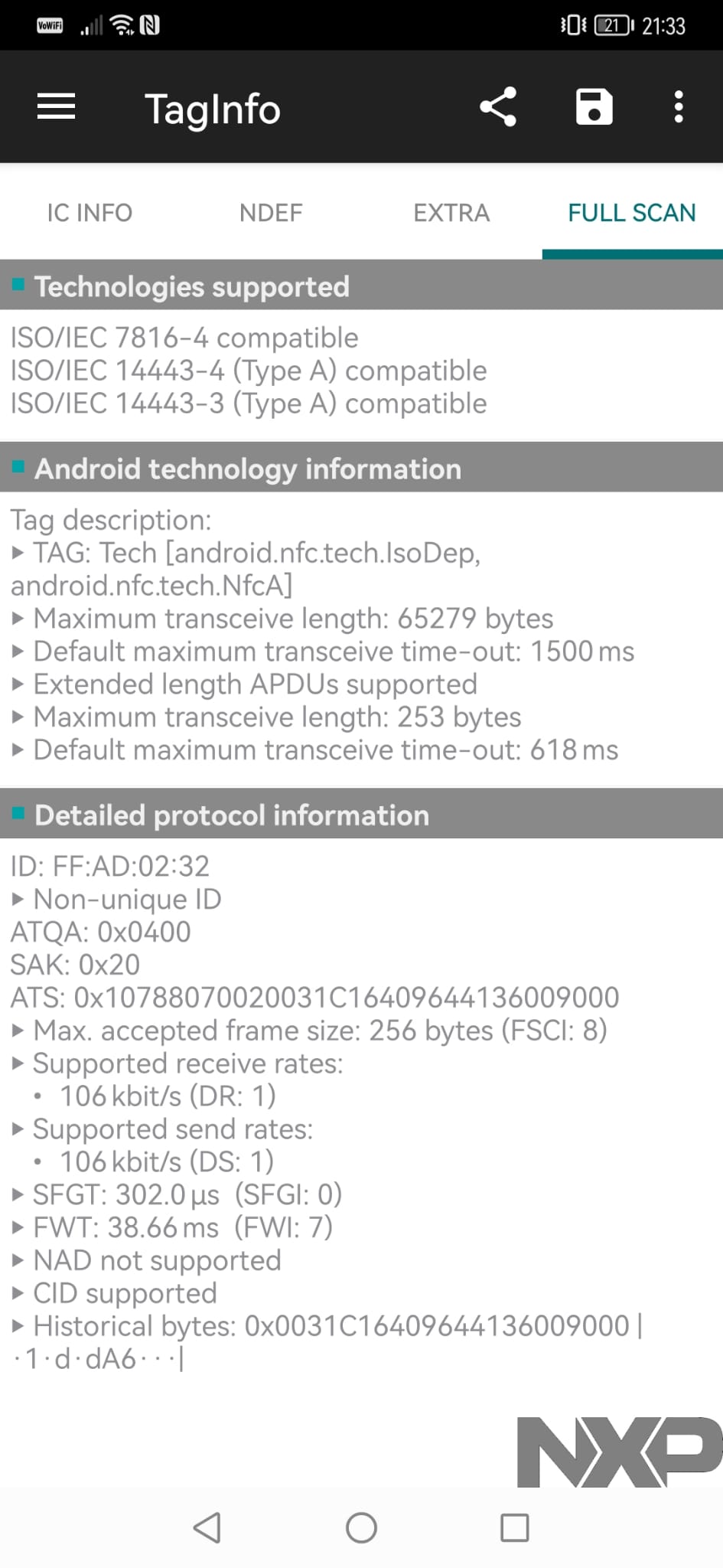
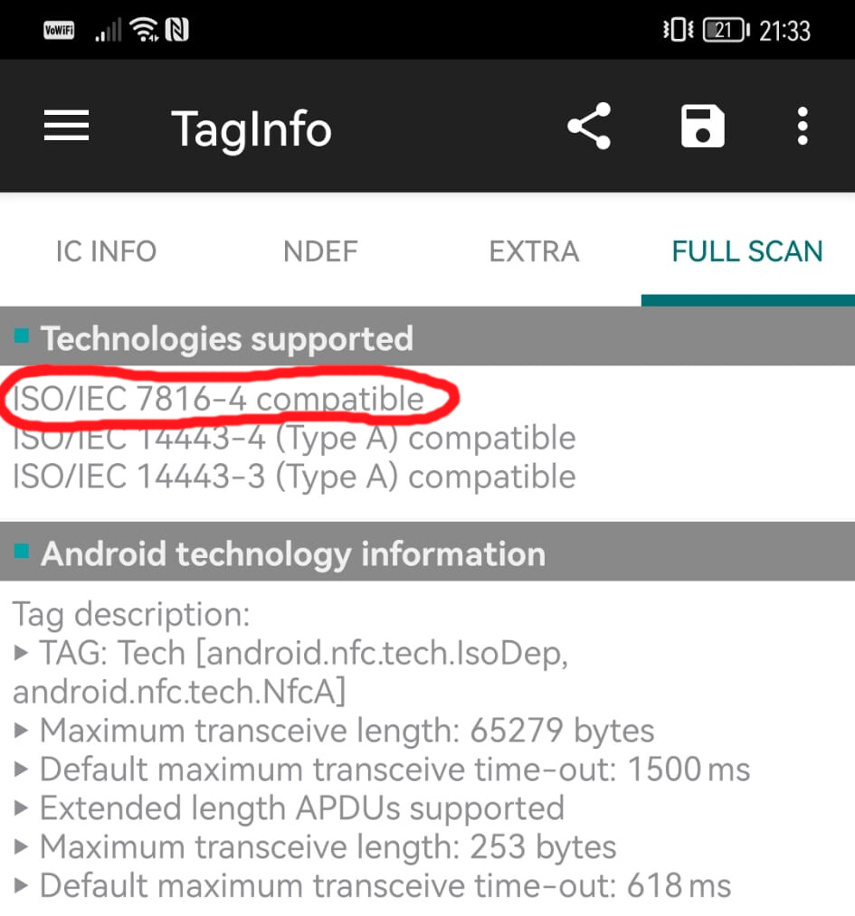
Under the “FULL SCAN” tab there’s a sub heading called “Detailed protocol information”. The first item there is “ID: [UID of chip]”
Hmmm, for some reason when interrogated those chips are using their MIFARE emulation functionality to identify as a 4 byte NUID. It might be because you’re using Taginfo. Try NFC Tools.
ISO7816 is a smartcard protocol so this is definitely a smartcard of some kind which is running mifare classic emulator. Often times this emulator is just turned on for no reason, it just came with the chip hardware and has nothing to do with the application.
Usually though TagInfo will find any related payment service applets loaded… but this time it did not. The applet IDs might be non-standard or the chip communication protocols might be presented in such a way that TagInfo didn’t bother to look.
Managed to get this working, now I have the manufacturer of the chip and get the UID each time, what is the next step to finding the model so I can look at the datasheet?
I did find out my Citibank card just plainly identified itself as ST25TB04K, but from the Chip serial how do we do this on other cards where it does not identify?
Well what was the first byte of the UID? Once we know the manufacturer we can take a look at their product line, the year the card was issued, and some features listed in the Taginfo to probably identify the card.
The easiest way to identify the capacitance is to melt the card and attach it to a known inductance, then find the resonant peak with a VNA, though. The datasheets that would have that information are often request only