Hey, I can help. For background you can check out this thread where I’ve compiled background info about making antennas. After this chat I’ll probably add a post explaining how to make repeater antennas for CoM modules.
If you plan to use the chips that are not a CoM module, it’s going to be difficult to solder a new antenna on directly. The problem is that a chip with a contact+contactless interface is usually a bare silicon die with a gold wire bonds connecting it to the contacts. That whole fragile assembly is then coated in a resin to protect it, and that usually makes it hard to access the antenna contacts to solder a new antenna on. You could cut the antenna wire near the chip but outside the resin, and carefully solder (splice) a new antenna you made onto it. I doubt it will work because it’s so fragile though.
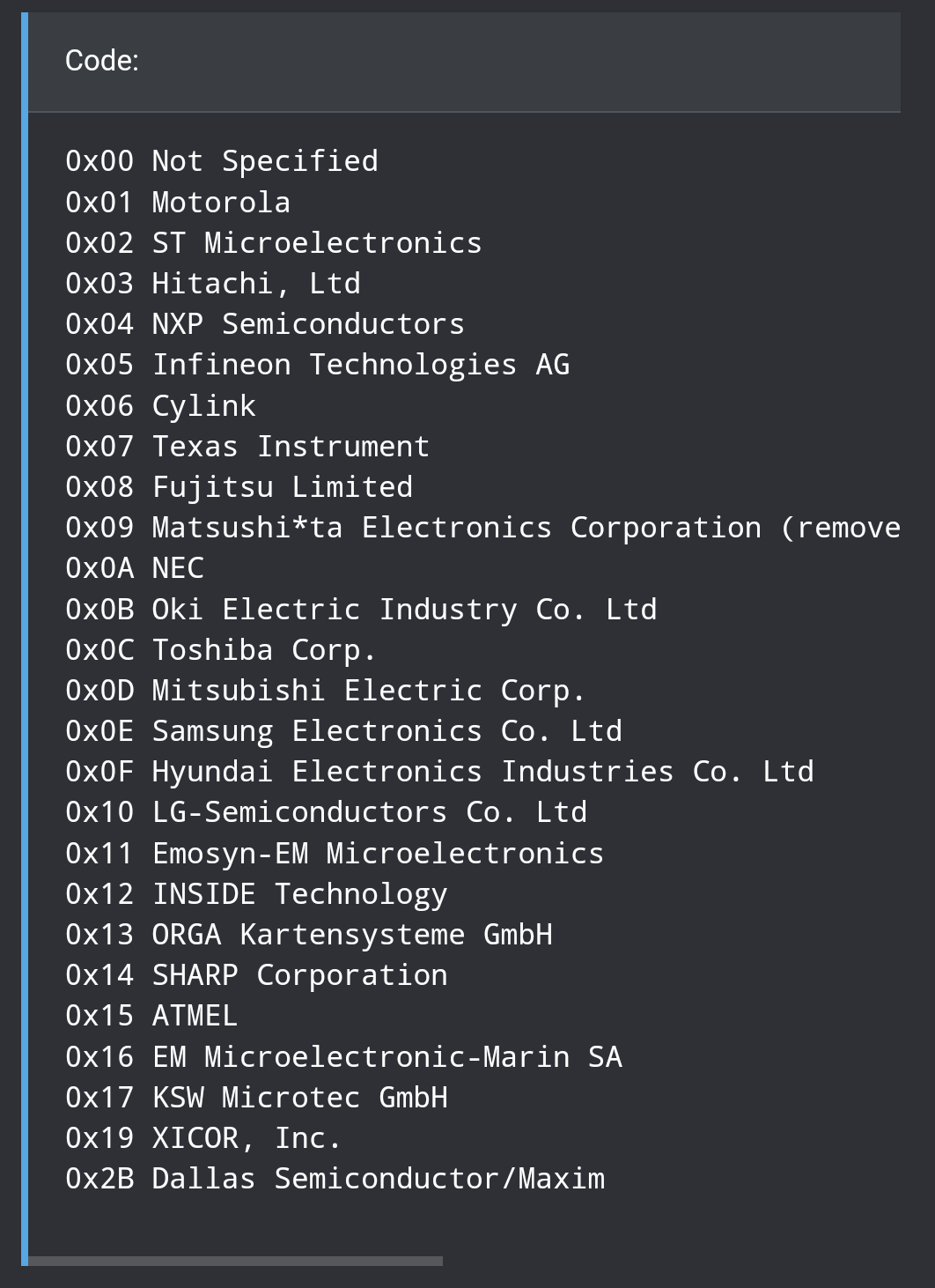
For identifying chips, the first step is to identify the manufacturer. Because of the ISO-14443a spec, any chip must identify itself with a UID when scanned. The first byte of the UID is the manufacturer code. Here’s a list:
Ultimately it doesn’t matter what type of chip it is, because you’re just going to present it to a reader and hope it works. You can’t reprogram payment chips.
If you plan to use the CoM module, you won’t be attaching an antenna directly to the chip, because it already has one. What you’ll be doing is making a completely separate piece that has a larger coil antenna and a capacitor to make it’s own self contained resonant circuit. We’ll call it a resonant repeater. When you place an appropriately tuned resonant repeater up against the CoM module (electrically separate but physically touching), it will shape and direct the field from the reader into the tiny antenna on the CoM module.
If that’s the path you choose, and you want more detailed information about how to do it, let me know and I’ll make a post about it in that thread and ping you.