Ditto. Not exactly the same parts but close enough.
I’ll report back when I have modified one of my readers. (I’m gradually building up a collection of microcontrollers and readers, I am up to 4 trinkets, two rc522, two Pico, and one PN532 (in transit). I’ll have to add a couple of ESP32 too.)
Cool, I just tested again. I have two trinkets hooked up to two different RC522 boards. My X field detector lights up with one board but not the other. The only discernible difference between the two boards is that one is a slightly darker blue (thicker lacquer coating perhaps?)
So, while it looks like the RC522 will work, the variability in quality is a potential issue.
I won’t show you my far from brilliant SMD soldering.
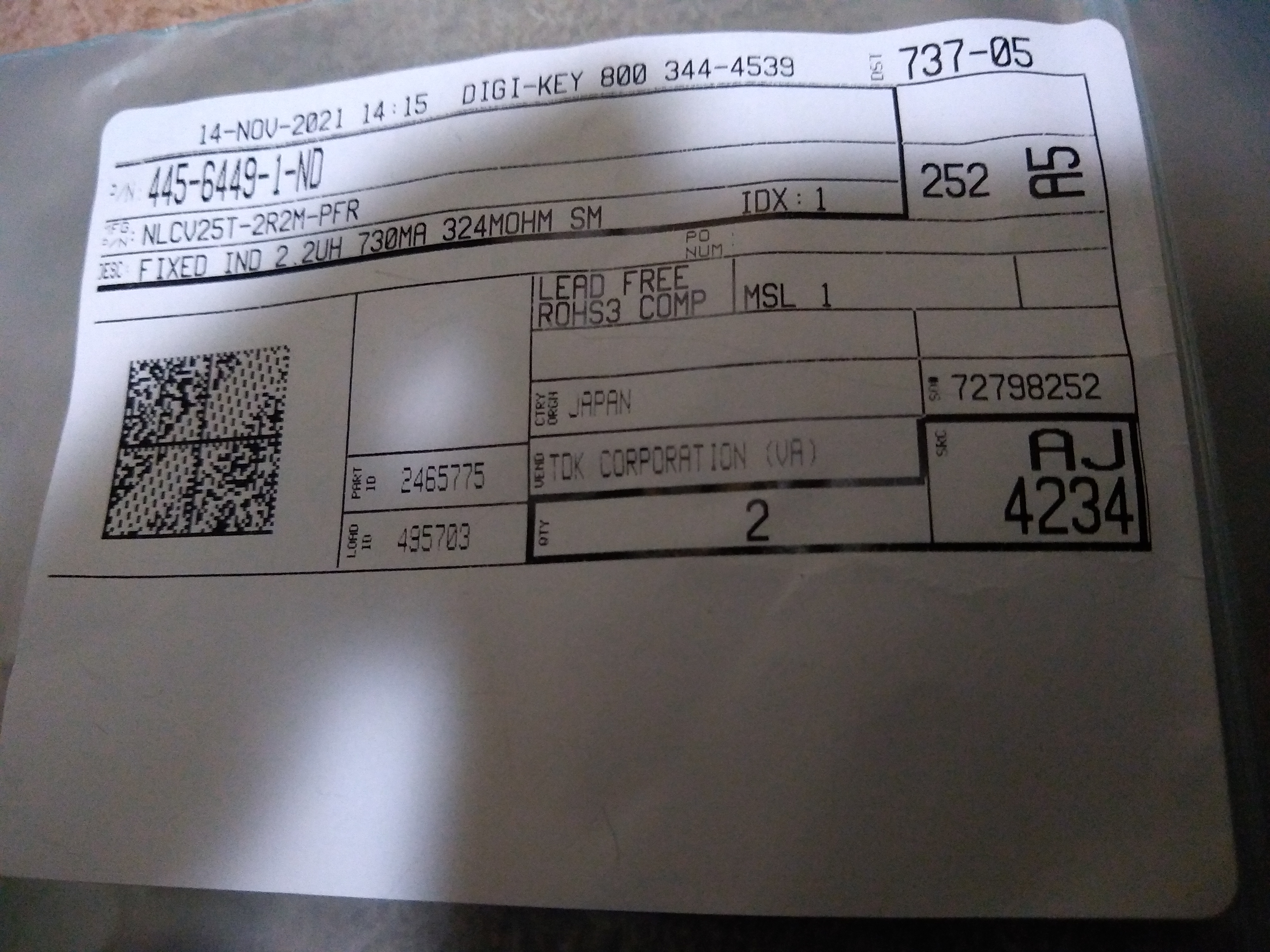
Incidentally the two inductors were shipped in this bag, wrapped in the packing list, which was wrapped in a sheet telling me to check the packing for parts, which was then wrapped in a packing sheet, which was in a box about 6" x 5" x 1". The carrier holding the two inductors was about the size of the letters bottom right on the label.
My RC522 also will not light up the field detector, nor will it read my xSIID.
Am still waiting for my components, since I bought them from some random guy on ebay rather than digikey. The fact, that I have been cheaping out on the shipping has really turned this project into quite the waiting game for me …
My implant is istll very new, but the phone reads it flawlessly …
The RS522 light up the xFD but I get absolutely nothing from the implant (I ditched the full case for the “open”/“half” with the. Exposed antenna on top)
The RC522 reads my NEXT implant perfectly fine, but I need to have the antenna touching my skin, and I need to have it perpendicular to one of the antenna straight sides.
Just tested my modified rc522 and it does now light up the field detector. However I still can’t get a read on my XSIID.
So the mod does seem to work, but the rc522 is still not an amazing antenna.
Also as it turns out SMD soldering takes practice. Ripped a pad off my first rc522 and burnt the makings off a coil on my second board.
It still works though
I have recently received my PN532 boards and I have been messing around.
I have not been able to get any of the example code that I have found to run.
The main roadblock for me is, that I don’t usually deal with hardware stuff like this.
Maybe my wiring is wrong? What is a pull down or up resistor. Why would I choose HSU or I2C or SPI?
Perhaps there is a better place to ask such questions, however I am not sure which learning resource would help me.
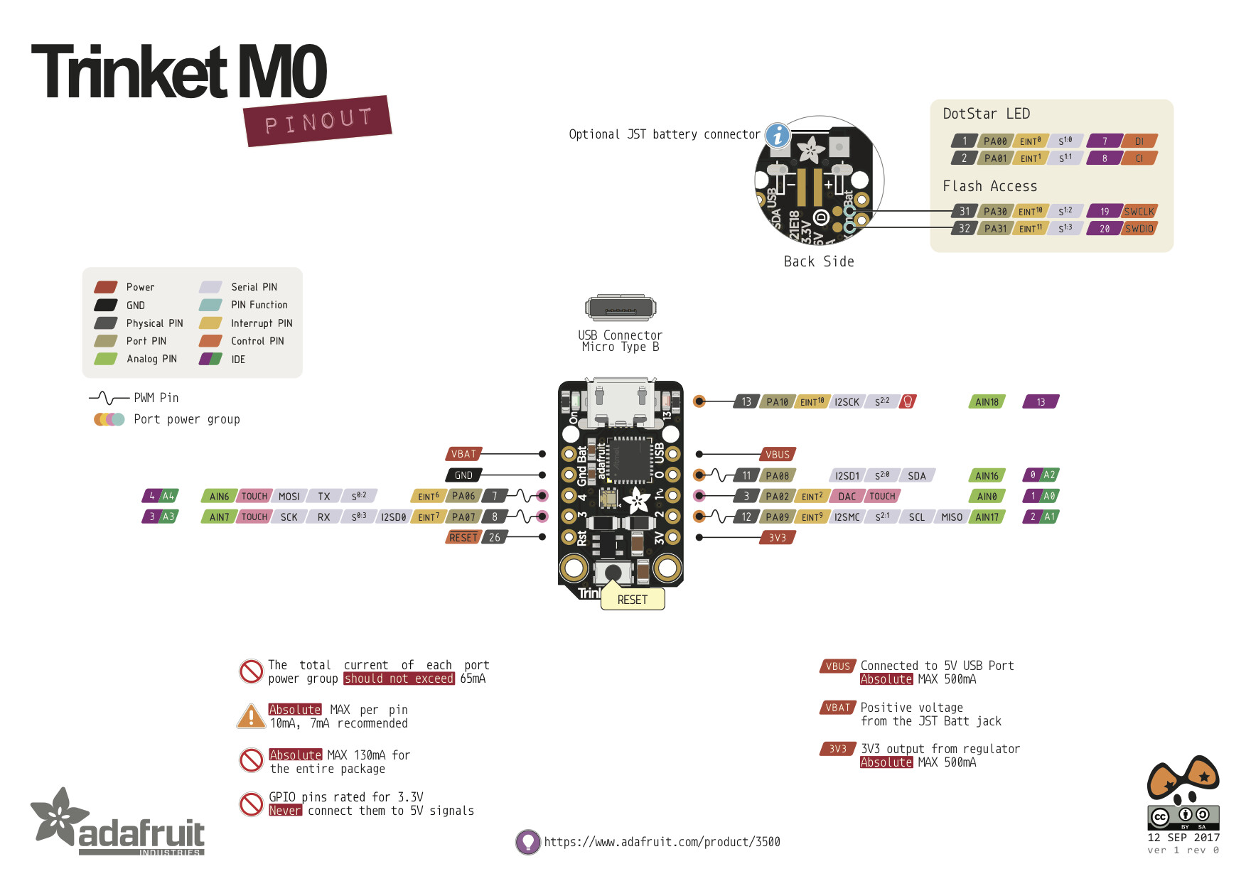
Would somebody be able to supply me with a working pinout for the trinket m0 and example code?
Pls halp.
Additionally I would like to mention, that I bought a PN532 from this place .
Visually it looks exactly the same as the PN532 V4 that I received directly from Elechouse.
So despite V3 of the board being depicted on the website, this seems to be a good source for PN532. They ship from Germany, which for me is infinitely faster and cheaper, than shipping from Hong Kong.
HSU is a High Speed UART and is basically a high speed serial connection. I2C is a different type of serial connection, it is usually slower but uses a lot fewer connections. SPI uses several connections and is a third standard. I was using SPI for my initial build.
I have been trying to get the iso14443a_uid examples from Elechouse and Adafruit to work. Am using SPI with same pinout as with the RC522.
The Adafruit example simply prints Didn't find PN53x board.
The Elechouse example behaves strangely. My serial device on /dev/ttyACM0 just disappears. Typing debug info via Keyboard.write also does not work. Can’t attach debugger … No try{} catch{} …
I really am lost. How am I supposed to debug anything?
I have my PN532 but I haven’t hooked it up yet. I am working on a complete rewrite that should make it easier to add additional readers, so once I have the rewrite done I will start looking at the PN532. My guess is that the elechouse version assumes you are using Serial, and so it shuts down the serial port… I haven’t looked at it yet though, that is just a guess based on the behaviour.
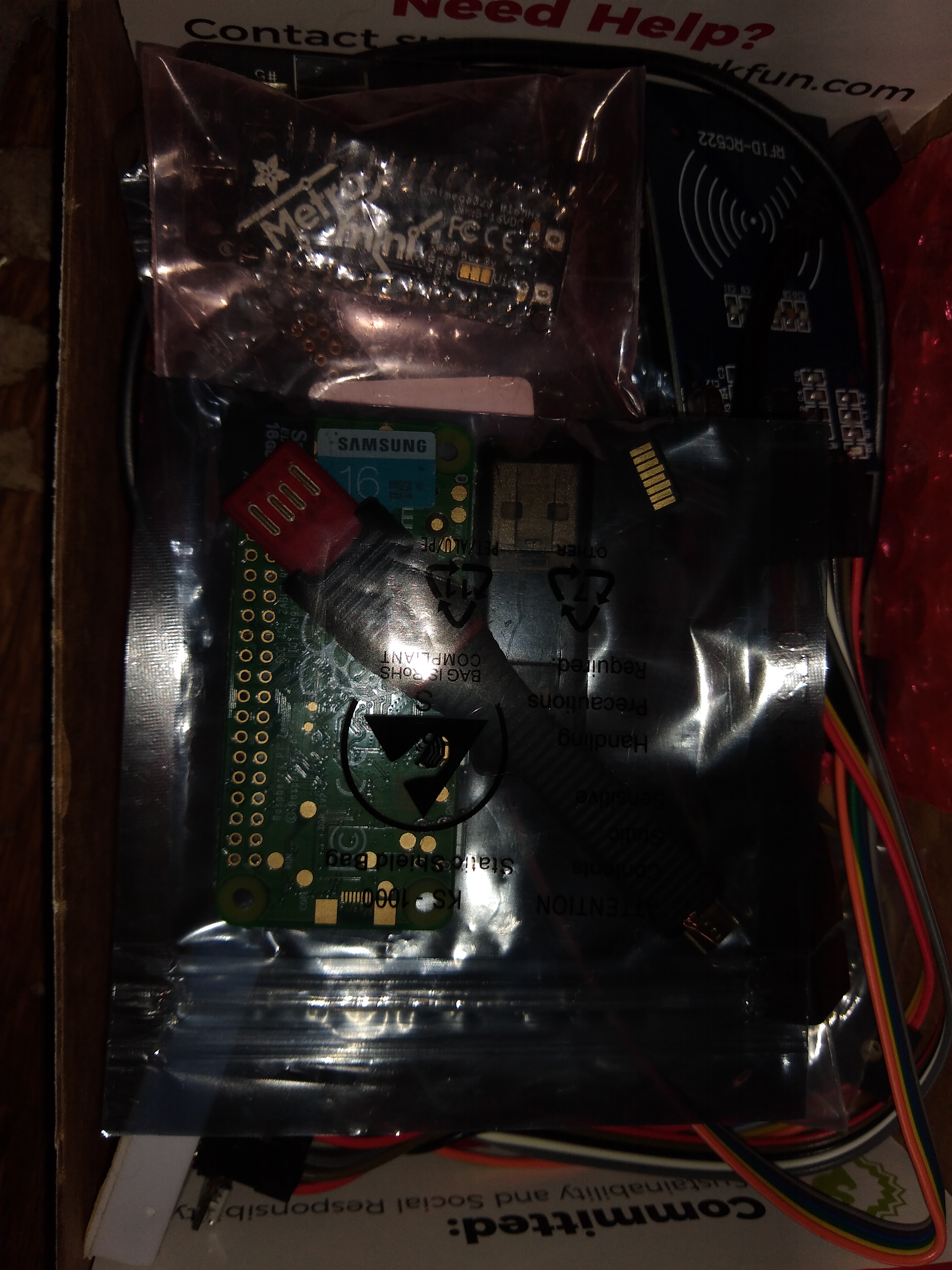
Well, you can see the raspberry pi zero 2 right there. I also have a couple of small screens one with two buttons and one with a joystick and two buttons. Those are for that. I’m going to start with just a disk image with proxmark3 software and an access point on it. Then add a screen and see if I can make it so that it can perform simple proxmark commands probably with the OLED screen with the joystick. Relatively cheap parts (under $40 for the Raspberry Pi and screen) and it is the same size as the pi itself. The pm3 would be unmodified.
Also in there are some Raspberry pico micro controllers, a Metro mini a trinket m0 or two, a couple of RFID boards, some Digistump Digisparks, some vocore2s,…
It’s a small cheap controller/computer box of goodness. (I need to add my Chip Pros to the box)…
After a night of sleep and some more messing around, i have gotten it to work.
After setting the Adafruit library to debug mode it sometimes detects the PN532. Not sure if it is a bad electrical connection, that is causing me issues, or maybe I have to increase some type of timeout value for the SPI.
The issue could be an SPI Frequency mismatch. The PN532 has a maximum SPI Frequency of 5Mhz. I believe lowering this number inside the library file Adafruit_PN532.cpp will fix the inconsistent connection.
Edit: OR you could use the Seeed_Arduino_NFC Library which was built with the M0 (SAMD21G) in mind. Evidenced by this SPI frequency clause inside PN532_SPI.cpp
#elif defined __SAMD21G18A__
    /** M0 spi library does not support SPI_CLOCK_DIV8 macro */
    _spi->setClockDivider(24); // set clock 2MHz(max: 5MHz)