Does anyone have any information on the pinout of the KBR1’s pcb board?

What do you mean by pinout? What is it that you’re trying to accomplish.
Pin-out; what the functions of the pins/connectors are on the PCB ![]()
1 Like
Ha, thanks I got that much. I mean it’s lacking specificity.
@DDCash
Do you mean what are the functions of the pins on the ICs soldered to the board, what are those little header holes connected to, what are the pads next to the USB jack connected to, what are those DNP parts about, where is the antenna connectors.
There’s a lot of questions to be asked here, but it would help to know why you want to know “information on the pinout” to pinpoint what it is you’re asking.
1 Like
@Satur9
I think he’s talking about the USB port.
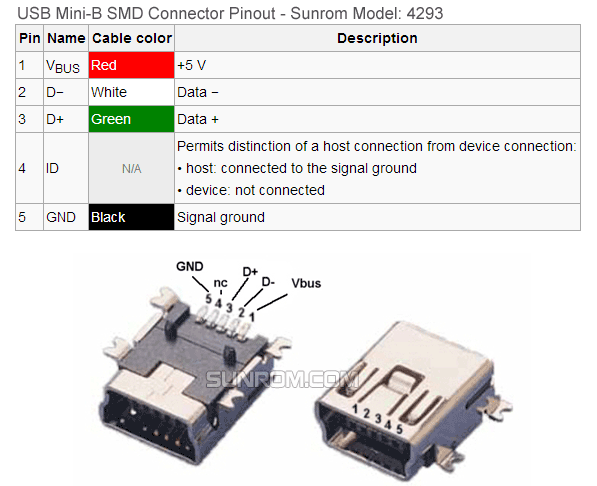
If it is only the usb pinouts, they will be the standard usb mini socket wiring ( same as micro also )
If I had to guess @DDCash may be looking at wiring into his computer…
1 Like
Yeah, Thats probably what he’s trying to do, sounds like a fun project.
A simple mod, but a good use of an implant
@anon67519447 are you going to do it also?
My thoughts, hidden to not derail thread
Yeah, I have been wanting to do my own laptop but my KBR1 has never worked reliably since I got it in my bundle, and it recently stopped working altogether. I’m guessing there is a loose connection somewhere.
I have hardly used it for that reason. I need to do some fault finding. Swapping cables (if I can find a usb mini in my box of cables) I pulled the unit apart and the solder looks good for the antenna, but I might give it another going over.
Otherwise I might need to grab a new reader.
The PCB and antenna are quite small, so will “easily” fit in laptop case; but behind the screen may be a tight fit and the cable run will be more difficult but I like the idea of behind the screen better (less chance of accidental scans)
Other than a “faulty” reader, my only other point of hesitation is the loss of an external usb port.
1 Like
No, but it does sound fun tho.
Edit:
Even if I wanted to my Samsung Chromebook Pro is to thin and delicate for all the extra stuff to put inside.
1 Like
Pretty much all those questions would be helpful. I’m wanting to know what the wiring schematic is. What the ICs are and yes what the header hole are for.
It looks like there are multiple holes for antennas( maybe 125khz also) that I’m curious about and other holes that have arrows by them. That makes me believe they are for leds. In that case are they GPIO pins that may be able to be utilized some how. Example: like a relay to turn the monitor on when you scan and when you lock the of the monitor goes off. Or you scan and it turns on your desk lamp also. Obviously those are probably pretty basic ideas but I’m just curious.
Nah I hadn’t thought about that. But now I am ![]() . This may be easier to integrate into my laptop with a small Arduino with an NFC board and with HID input. This KBR2 board is a bit bulky and has unused pads on a 1/4 of the board which is wasted space in my opinion.
. This may be easier to integrate into my laptop with a small Arduino with an NFC board and with HID input. This KBR2 board is a bit bulky and has unused pads on a 1/4 of the board which is wasted space in my opinion.
Those sets of 3 header holes with the arrows on the bottom left of your picture are definitely for more indicator LEDs. They’re probably bicolor (green and red). All the header holes that are square connect to ground. I would bet those sets of 4 pin headers in the middle are programming interfaces for the ICs.
1 Like
Also don’t forget the Chinese are economizers… depending on populated components, that PCB probably works in the KBR1, a can opener, and a laser guided missile guidance system.
12 Likes
Can you use the KBR1 on a ASUS Chromebook? For password login by tap.