Eyyy good news, the key works superb on the 3.3V supply from the arduino (altho teoretically it uses a 3v battery) so protyping is super easy, also the buttons to close/open the car work nicely even when the keyfob is in the car, so now i just have to hook up some transistors to replace the buttons, and a relay for the 3.3v power supply, then i can test it with a button or something else i have lying around (before i buy a rfid reader :P)
also the battery terminals in the key are laaaarge, so no problem soldering, the button terminals however… not sure how to go about doing them… also other soldering points very close to them, so i cant really over dimension it…
got wires onto the battery terminals and that worked, got wires over one of the buttons, that worked, tried to get wires onto the second button, PCB got darker, and on the other side of it was an IC -.-
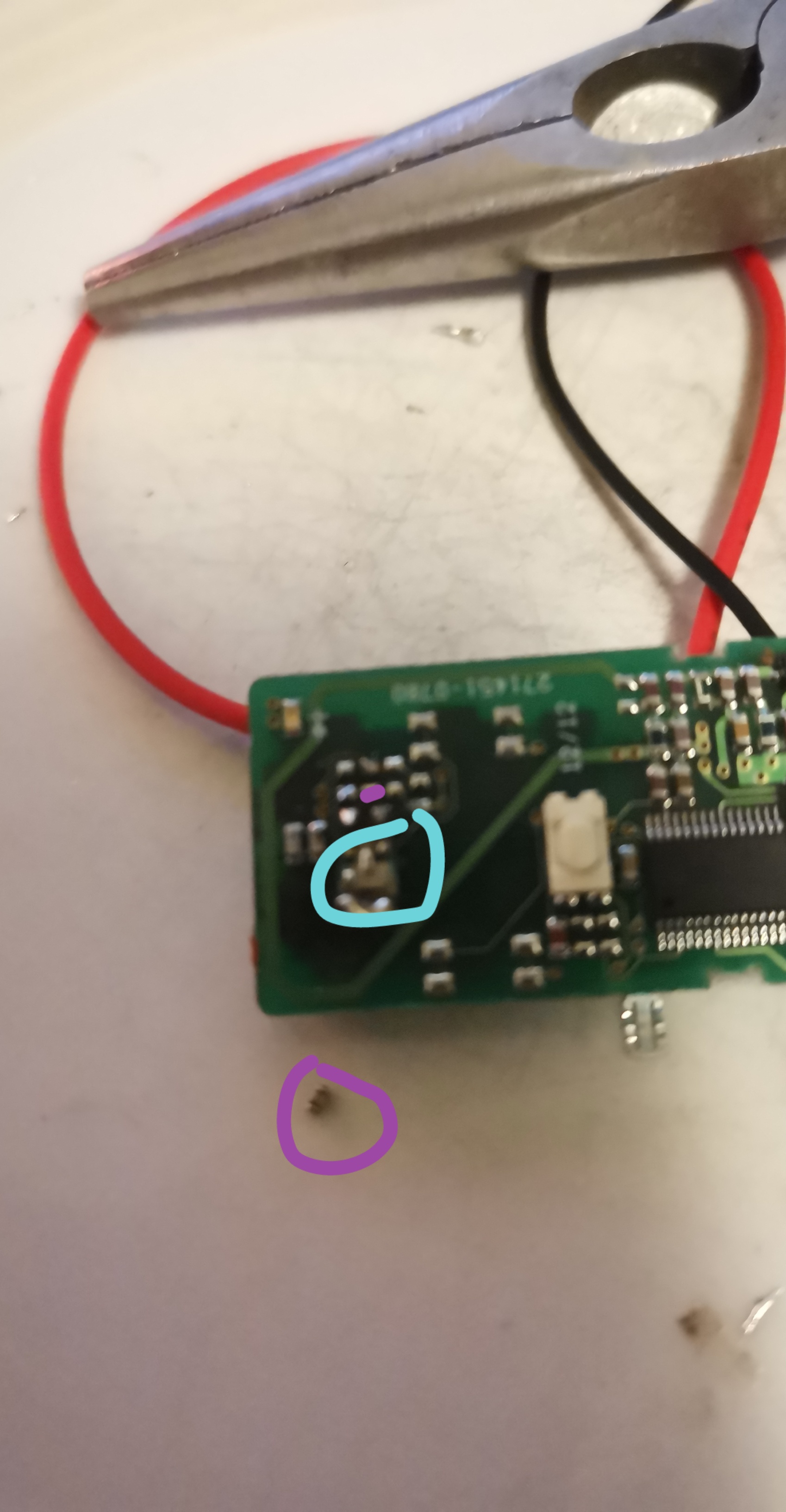
EDIT: A resistor fell of im dead… Picture for reference, that mini thing was where the same color is on the PCB… Right enxt to the button, were talking like a few mm
I’m currently planning a build of this style system, but for a proximity keyless entry (basically we do the battery thing but toggle it on/off for implant taps).