You wouldn’t be able to do it with a passive tag. That’s just not how the coupling works. You could have a battery powered device that generates a high amplitude signal and synchronizes it with the reader, so that when they’re held close the reader experiences 10x the voltage.
That would only serve to burn out the delicate components making up the readers analog front end. I suspect in your hypothetical scenario the purpose would be to force retailers to replace the shitty MX915 terminals. Unfortunately in this case the terminal would still work for insert and swipe, and the staff would just ignore it and say “oh yeah we can’t support tap to pay on this terminal anymore”. Even if they did send out to get it replaced, the company would just send them another MX915. The terminals are cheap ($150?), It’s the controller that runs them under the register that’s expensive and why they won’t replace the systems
No none of that, while I dislike the reader I don’t support that approach… self defeating and just taking it out on the wrong people
It was more of a solution looking for a problem…
I’ve just always appreciated the simplicity of the usbkill method of attack, “take what’s given and shove it back the wrong way” was just curious if it could work on a rfid principle
Sure you could use a battery, it was just satisfying of a concept to use supplied power
Okay so, technically this would be possible. There are booster chips from ST that can in theory be powered by a large secondary inductor coil. This would actually work quite well for the MX terminal because it puts out a fuckton of energy. The terminal is so bad with passive transponders because it is designed to talk to phones at large distances but basically ignores the nuances and frankly stomps on communication efforts made by passive transponders. Because of the vast available power coming from these terminals, you could effectively use that power with a large secondary coil to turn your passive transponder into an active one through the booster.
The downside here is that the booster chip requires a direct connection to your transponder and not an inductive connection.
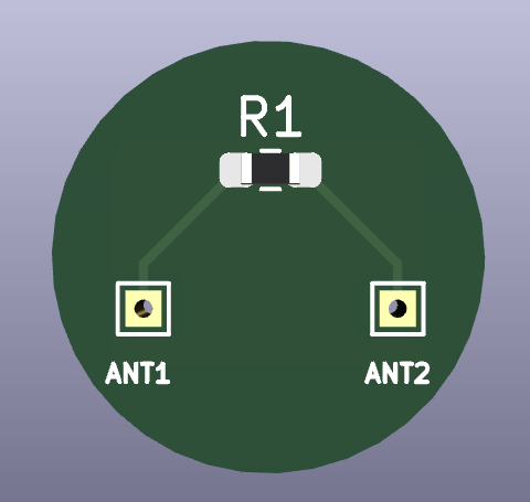
Essentially you can get the coil from an already made rfid chip. Use the calculator to find the correct resistance needed. Clip the old chip off the antenna, and solder everything in place. the board will fit in the middle of the antenna as it is only 11mm wide atm.
The next step in this would be resurrecting the old NFC Amplification Sticker project. I may start looking into that and creating a flex antenna inlay. but i just dont have the experience or knowledge to create that yet.
Anyways i sent this off to china to have a few of these made in fr4 and some flex, we will see how they turn out.
If you want any help with that lmk. I just haven’t had a lot of bandwidth or money. I learned a lot from the CoM conversion though so we could probably make a repeater without any external components
Are you thinking Onboard capacitors using a special footprint?
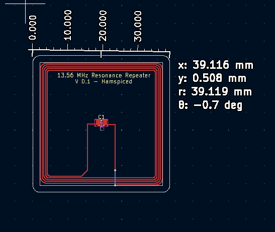
Using an Antenna Generator i found online, i have a preliminary board mocked up for v0.1 of this project.
I want to get a few prototype boards made in 1.4 and flex to measure capacitance and see what i need from there. Always willing to have help from someone vastly more knowledgable on the subject.
My v.0 test boards should be arriving next week. i havent sent the order for these yet.
the other test boards from my post above will be using a bunch of pre-made 13.56 antennas from some aliexpress chips. they have a small footprint though of around 15mm. this new design is larger (i struggled achieving a round spiral antenna in Kicad).
Before you spend a bunch of money on flex (I recommend JLPCB for your first few flexes because they’re cheaper btw) we could voice chat in discord and I could go over some stuff with you. I’ll be around today. Otherwise I’ll just post a little guide here. Lmk what you prefer. I can also review your boards before you send them out pretty much whenever you need.
I’ll try to put together a post about the onboard capacitor plate calculations today or tomorrow, but for now I can say the easiest way to make circular traces in most PCB software is to make squares and then round the corners with a radius value that is half the length of the trace
Reading through your git it looks like you used the same generator I found on kicad forums to make the antenna. I’m gonna try to tweak it a bit to make it more circular but yeah design is almost identical
I also received my new Pixel 8 today so just in time to add these to my case.
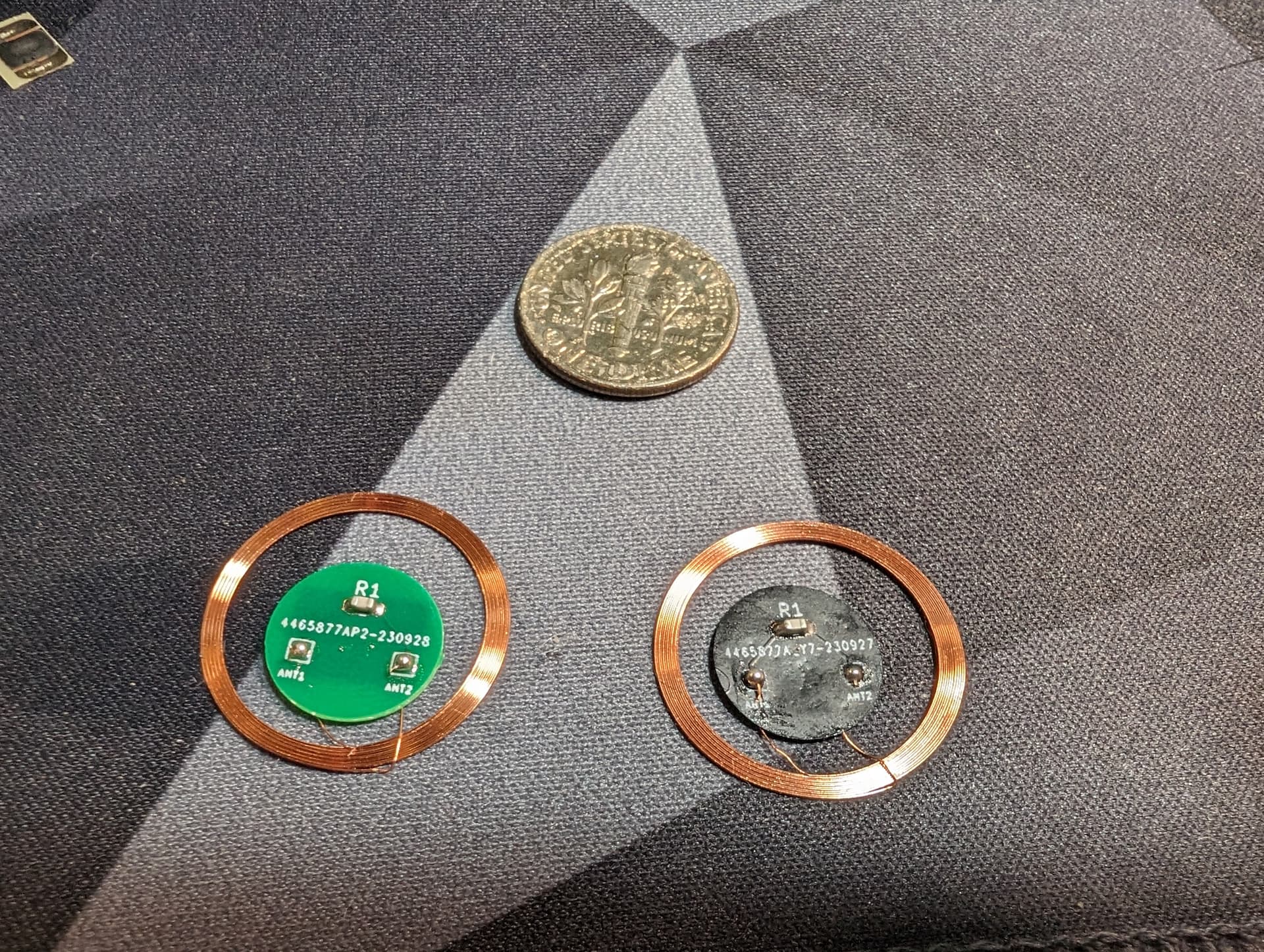
Soldering went easy. Surprisingly enough is easier to hand solder these than to use the hot plate. Much easier to quickly create these. I also ordered a shit ton of boards because it was literally pennies more. If anyone wants one and is in the US I’ll send you one and I’ll cover shipping.
@Satur9 since I now have some more time, I’m going to look into maybe resurrecting the old idea of the antenna sticker. Let me redesign this circuit to be circular and I will reach out to you regarding the integrated capacitor.