Hell yeah, decluttering desks one repeater at a time!
6 Likes
Here’s the real kicker: It can even read my NExT through the desk!!! ![]()
6 Likes
Obviously just the ntag side, not the T5577 right?
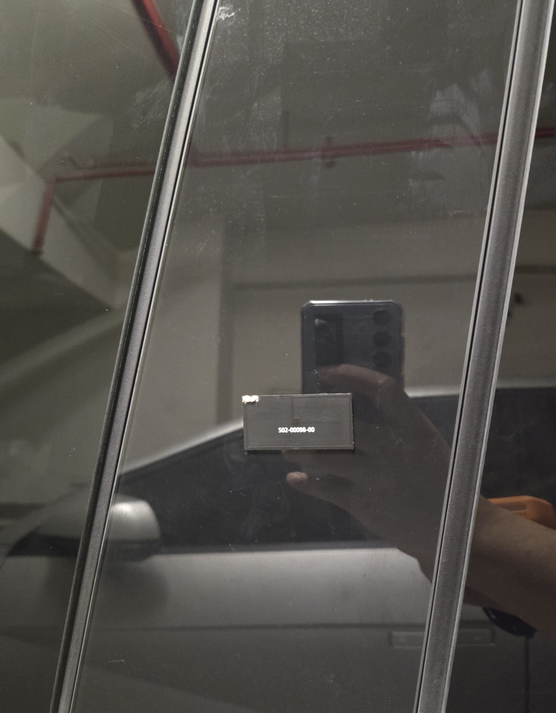
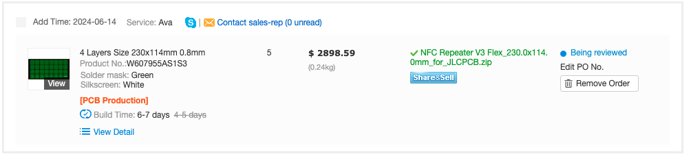
Sharing my DIY version.
Antenna is 800nH ($0.4), and capacitors are 100 // 100 + 560 // 680 = 172.22 pF.
Now I can unlock Tesla vehicle with Apex up to 1.5cm to the antenna.
Without antenna, only 2 out of 10 attempts were successful.
4 Likes
Great work! Please keep us posted! I’m super curious to see how this holds up in weather, rain, etc.
2 Likes
Yeah, I’m curious about the Sun ![]() / heat
/ heat ![]()
Looks good by the way,
Is that a Cyberturck? Perfect vehicle for a Cyborg ![]()
1 Like
Made some excellent progress.
V2.1 Small Repeaters
Now available.
I’ll be updating and releasing the Gerber files on GitHub soon.

These Are pretty slick.
Flexybois
Also complete. My version is finally in a state I can start trying for production prototypes. This I’ll be naming V3 or V3F for Version 3 Flex.
In my testing they operate pretty well but I am noticing decreased performance when compared to their FR4 big brother. When I get my production units in per usual pilgrim will get a batch for testing.
FR4 Revisited
So I have realized that there is a pretty annoying flaw in these units. For the most part it will go unnoticed to any one that has gotten one from me. I test each unit before it ever reaches anyone. The green boards themselves were hand soldered by me.
For the smaller FR4 V2.1S repeaters I had to switch to a different capacitor with tighter tolerances. +/-10% were really killing the performance on these if it was on the upper end of that tolerance. Not to mention I switched to having these assembled at the mfg rather than me doing it. The new batch have a tolerance of +/-5% and perform significantly better.
Taking what I have learned in this journey I’m going to attempt to revisit the FR4 repeaters in hopes to create an entirely passive FR4 board. Not positive It is achievable but with the current stackups that are available I think I might be and to achieve it on a 4 layer PCB without losing much efficiency.
I have a full panel out to prototype and return. I have a generic idea I came up with a few nights ago and I mocked it up in kicad this morning and sent it off for fabrication.
My idea is take the two known good designs we have for the V2.1 and turn them from a 2 layer board, into a 4 layer board.
The stackups have a prepreg layer in between layers 1 and 2 and then in layers 3 and 4. The FR4 core is only between layers 2 and 3.
So my design is as follows.
Layer 1: copper trace antenna with end A and end B terminate into two vias that bring you to layer two.
Layer 2. Via A takes the trace to the end of the board and terminates into another Via that goes through the FR4 core into layer 3 which connects to a capacitive plate. Via B travels a similar path and terminates into a Via that goes through the FR4 core into layer 4 and connects to the bottom capacitive plate.
I’m my mind the concept works. The current FR4 repeaters work fantastic going through the same thickness FR4 core.
So we will see. Jlcpcb is running a deal on 4 and 6 later 50*50mm projects for 2$. So I mashed together an array to test out. I’m optimistic I can do this. I’ll keep y’all updated
9 Likes
These look awesome! I suspect there’s a chance I’ll need one whenever I get around to chipping myself, and that chance is partially because of the literal piece of metal(latch slipper, picked up after having two cases of being stuck outside a door from someone kicking the doorstop, with the keyholder tending to a situation elsewhere. Fun times /s) that lives on the back of my phone(though it doesn’t completely inhibit reads, as I still get nuisance scans of my bank card through it). Worst case, I can move the metal around slightly in an attempt to decrease it’s interference with the antenna if it does prove to be an issue in its current location, no biggie.
You’ve done a great job on these board, and I’m sure they’ll only get better with each revision. Bravo ![]()
4 Likes
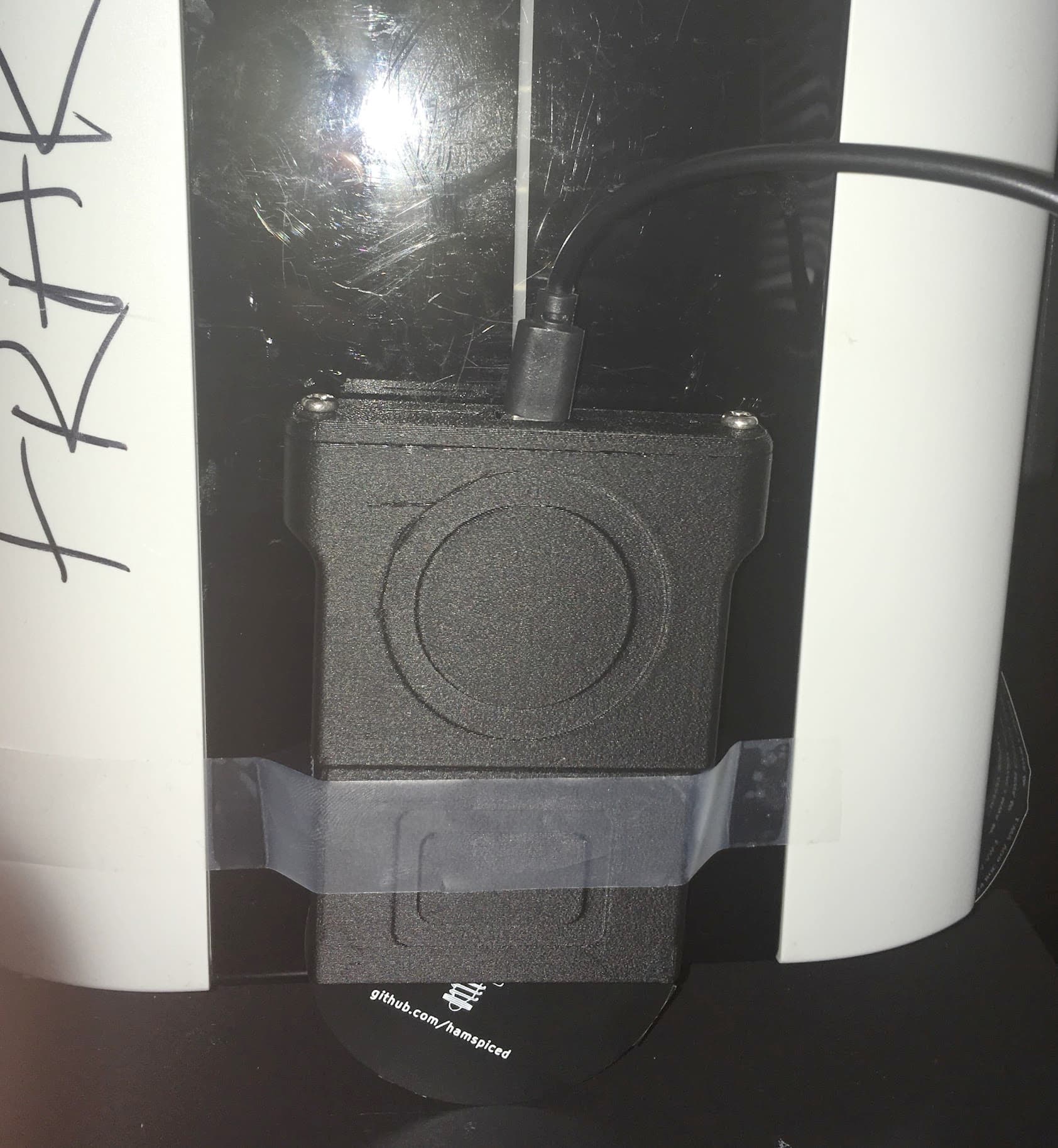
They work great in the testing i have done with them. They read through hollow core doors, my phone case, my wifes phone case, my desk. Ive gotten some great feedback on them so far and i hope that if i can get the design working on 4 layer PCB’s it will only get better. But there is only so much this single project can do. I have another project i am almost wrapping up on. that will be a fun one to release to the world once i can get back into it.
4 Likes
Indeed they are.
You have made quite the arsenal.
I was more than happy with the V1, and they have just gotten better and better with each revision
2 Likes
Amazing progress @Hamspiced
If you have some for sale, I would gladly buy a few. BTW I pm`ed you. Tnx
1 Like
(“Shut up and take my money” gif of Fry)
But for real, where can I buy some of these ?
You can shoot me a pm.
2 Likes
@caj380 gave me one of these V2 Large ones and it worked perfectly for what I need. I am using it with a proxmark3 Easy running Iceman.
I’d love to get my hands on more of these!
3 Likes
feel free to shoot me a DM
1 Like
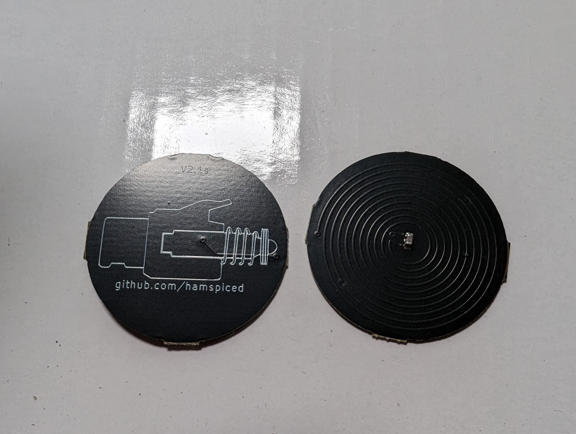
Since Amal has released his Repeater stickers i figured i would update my posts here.
Repeater stickers are now available on the DT Store. These are different than the ones i came up with which imo are a much sleeker design.
Mine are also complete and i will be updating my github soon on my process but i will document it out here as well.
I did 3 panel runs in total after i came up with my Antenna design. The largest issue i had was that the Antenna for the 2.1s was covering almost the entire PCB and had no room in the middle for the capacitive plates. My talk with @Satur9 he suggested i move to a double layered antenna design using a via. Brilliant suggestion by the way because it opened up the PCB for me to use the middle for capacitive plates.
This is what i came up with after doign the math to ensure my turns were going to be about the same.

Satur9 was awesome ina provided me with some documentation and math on how he created his design and i used it (unsuccessfully) in estimating the approximate capacetence that i needed.
C = ε0 * εr * (A/d)
- ε0 (vacuum permittivity) = 8.8541878128⋅10−12 F/m
- εr (relative permittivity): = 3.4
- A (area of plates): 1cm2 = 0.0001m2
- d (distance between plates):
- 0.025mm for 0.26mm FPC thickness
- 0.012mm for 0.1mm FPC thickness
Now i knew that i had a desired capacetence of 100pf for the trace thickness and length for my V2.1 repeaters. I assumed the design i have now would net similar so i plugged my values in so i could find the area needed for the capacetive plates.
These panel runs are pricey so i wanted to err on the side of caution. The math told me that with the capacitive plates that were at .2028 radius id achieve 100pf capacetence. I am bad at math so i made a grid and went up and down incrementally. I had hoped i was on the money in the first try, but knowing my luck i paneled it out. I figured if i could get something “near” tuned i could do another run and zero in my tuning.
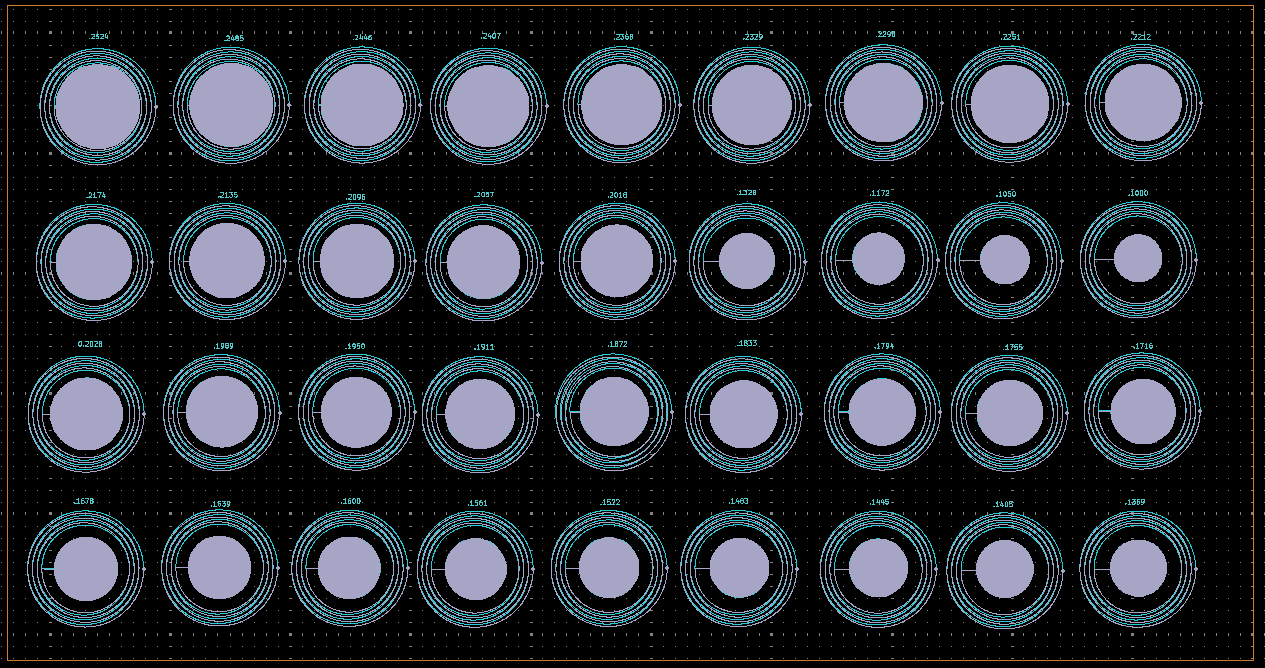
Im basically caveman style tuning here bruteforce style. This is expensive and not reccomended.
When they came in my suspicions were correct and i was wildly inaccurate. However i had promise with the .1000 radius repeater. on the last column of the second row.
So i bruteforced another run. this time i did the same style run, but i was zeroing in under .1000 radius plates.
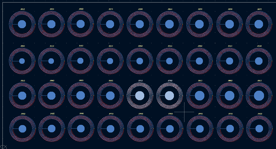
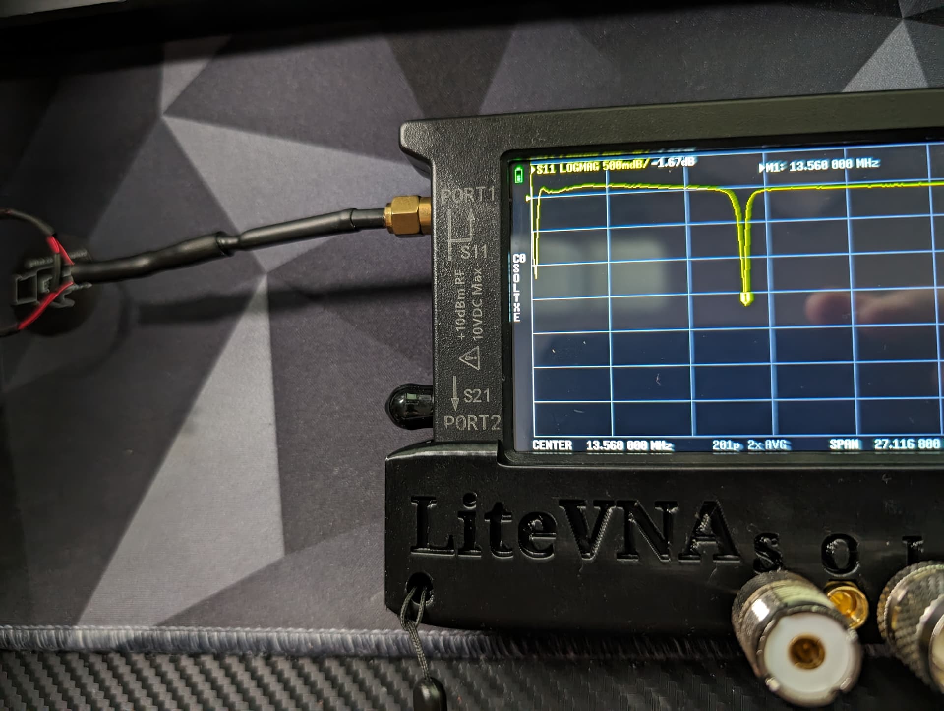
At this point i had incredible promise with tuning between the two highlighted repeaters. I was getting proper readings and i was within the power curve at 13.56mhz. So i wanted to tune this perfectly. I figured one last prototype run and i would be good for production.
So i had a great amount of data i could collect at this point. i then got all of the repeaters i have made in flex, and I plotted where each repeater lined up in frequency given the radius of the plate. At this point i abandoned sensible math and just went for it.
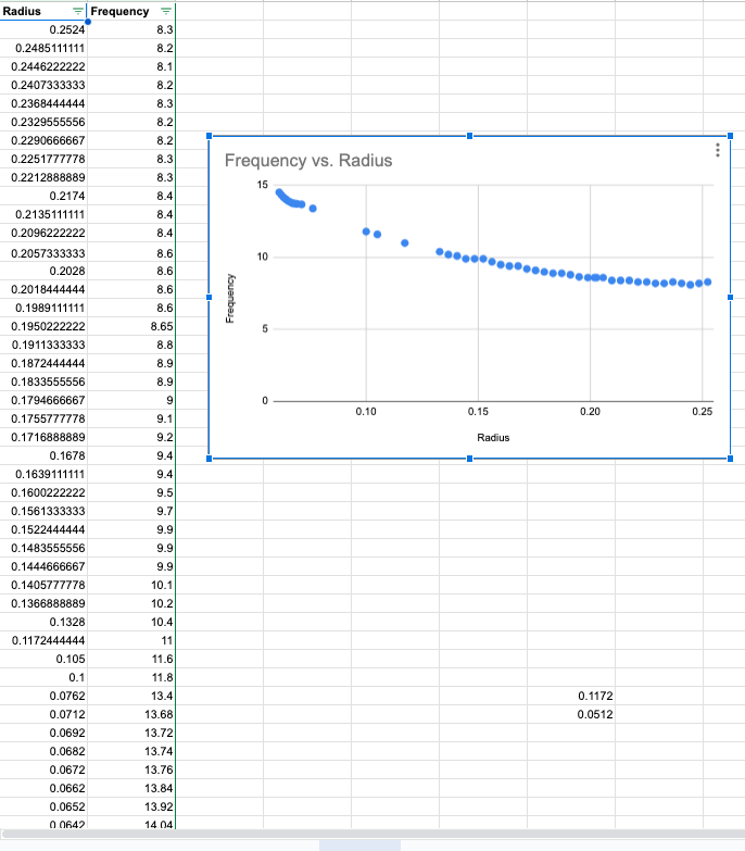
I knew i would have proper tuning between .0712 and .0762. So my final run was to find the exact capacetence needed with the correct plates. my final run was more of the same.
TLDR;
I found it.
This project has been a hell of a year for me. I was talking with @hoker about this last week… Prior to this project i had never considered PCB design. Didnt know a thing about it. Hell i didnt know much about NFC in general. This project was picked up by me only because i was upset my damn brand new Pixel 6 couldnt read my xSiid through my nice phone case. I stubled across a few threads of Satur9’s and @Az_F and made a shitty repeater from an old fob and it just kind of grew from there with me spending many late nights trying to figure out Kicad, and learning how to make a bom, and fighting with different fab labs.
This has been a wild ride. Appreciate you all for sticking with me as i worked through making these things, i appreciate all of those that have tested them for me and took time out of their day to give me feedback and provide some insight, Also huge fucking thanks to @Satur9 for listening to me bitch on Discord and taking time to help me understand some of how these fields are generated. 30min talk with you helped me more than weeks of googlefu.
For me im calling these Flex Repeaters done. I wont be releasing the final design for these on my git. i feel like if someone wanted to make their version of this, reading the process involved here is more than enough for them to be able to make their own at this point.
What about the FR4 repeaters?
So… their design as posted to the git is perfect for what they are. imho they have the best range and operate fantastic as is. those remain available to anyone under creative commons.
the Large V2.1 is getting an upgrade (Hopefully). I took what i learned here on the flex repeaters and i have a prototype board out to the fab house. Pretty confident i can make the large repeater passive.
The smaller V2.1s. I believe it is possible to make this passive too, range will be shit, if it functions. however i will not be prototyping this. I made a tester board to see if i could, but the design relies entirely upon having blind/burried via’s and they are INCREDIBLY expensive to fabricate.
If the production cost for blind via’s goes down on 4 layer PCB’s ill revisit but for the time being there wont be any upgrades to the V2.1s any time soon. ill update this thread if the V2.1 Large repeaters become passive.
With that said again i appreciate the community here for the encouragement and the help getting to the end of this project. Just wanted to say thanks!
11 Likes
That’s interesting, I have a Pixel 6 as well and have a shortcut to Google wallet on my xssid that I use daily and don’t really have an issue scanning it ![]() it’s not great but reliable enough now that the position is muscle memory. I guess position and depth matters a lot. Mine is between the metacarpals and the way I scan it is by having the implants in between the two phone’s buttons, perpendicular to the phone’s edge. I also have to straighten my fingers so that it pops up, it doesn’t work with a closed fist. In that specific position it works well.
it’s not great but reliable enough now that the position is muscle memory. I guess position and depth matters a lot. Mine is between the metacarpals and the way I scan it is by having the implants in between the two phone’s buttons, perpendicular to the phone’s edge. I also have to straighten my fingers so that it pops up, it doesn’t work with a closed fist. In that specific position it works well.
Anyway congrats on your project! Pcb design is something that always intimidated me and I never had the nerves like you to try it out ![]()
i use the Peak Design phone cases. They are super sleek and they have magnets for magsafe chargers. They are really nice cases, but really bad at letting that NFC signal through. I was never able to get a read through the case unless i had a repeater on it.
3 Likes
Hell yeah, awesome job man. Quite the journey. This rando on the internet is proud of you