Disadvantage to deep sleep and only waking it up on scan is you wouldn’t be able to trigger lock and unlock remotely.
Personally I feel like that’s an advantage. I don’t think it’s a good idea to connect stuff like that to the internet.
2 Likes
I run homeassistant fully isolated on an IOT network with no internet access. It’s nice to lock my doors at night automatically based on if my bedroom lights are on or not. But we could make a non networked firmware that would be fully air gapped for the people who don’t want a networked lock. For that matter a firmware with a hard coded implant ID as an option might also be nice so that no one could find an exploit that lets them get the lock into adding a key mode. Options are what’s nice, multiple firmwares are inevitably going to be available on an open platform.
1 Like
Adafruit QT Py ESP32-C3 WiFi Dev Board with STEMMA QT : ID 5405 : Adafruit Industries, Unique & fun DIY electronics and kits This board has a wifi option (can be turned off if you want), i2c and spi for talking to a reader, usb-c is nice, and extra pins for closed door sensors or other stuff if we want later. This chip in deep sleep also takes 0.3mA so it should be able to last a very long time even without a solar panel.
Then once a long battery life version is all worked out a custom board can be made. But it would also be cool to have it work with all off the shelf parts if someone wanted. This board is also open source so it should be pretty easy to make into a lock controller board later on.
Agreed.
What’s the reason range on the PN532? Does it read through a door? My target here is the apartment dwellers who can make little to no permanent modifications to their door. There also can’t be any wires visible anywhere. The only way I can think to do this without a reader that can read through doors with x series implants is with a separate wireless reader. I’d like to make the reader and the door lock communicate through Bluetooth since it can be very low power. Reportedly down to 10mA with the Fire Beetle.
On a different note here’s a servo
ZOSKAY 1X DS3218 Update servo 20KG Full Metal Gear Digital servo Baja servo Waterproof servo for Baja Cars(Control Angle 180) Amazon.com It’s cheap but not too cheap, and has all metal gears. Has an operating voltage of 4.8-6.8v. not sure the current draw but I’ll easily figure that out once it arrives.
I think a prox sensor would be best for activation. You can adjust them where they only enable within an inch or two and require less finesse when carrying awkward things.
Checkout the homeassistant reader thread where we’ve talked about pn532 a lot recently. I have some newer readers on order to test out that should have much better read range or at least very thin wires that are thin enough to work around the corner of a door
But currently the read range is pretty short, meaning you’d need the reader on the outside of the door. I have some ideas for non distractive wiring to the outside of the deadbolt but need the new readers to really test it out.
PS) your link doesn’t work
Link should be good now. Wiring is a no go. Strictly against my lease. Also with poorly fitted doors they will break. Things like Ring doorbells are okay but they don’t want exterior wiring showing.
Got the PN532 today and got it working with I2C on a nano just for sanity. I have a fire beetle on the way as well. If we don’t end up using the fire beetle I have plenty of other projects it will have plenty of use for. I’ll at least get the code written and working on a nano for now. The servo that came with the Arduino kit I have it is a POS so we’ll have to wait for the better one to come in before I can really test with it.
In the meantime…does anyone have 3d modeling experience that’s willing to design the housing? I was thinking of something similar to the switch bot where it just grabs onto the thumb turn on rather than something like Augusts design which requires removing the original thumb turn
I can model a housing for just about anything as long as I have measurements. I’ve been modeling for like 10 years.
Awesome! Thank you. If you base it off a standard kwikset deadbolt then it should fit most deadbolts.
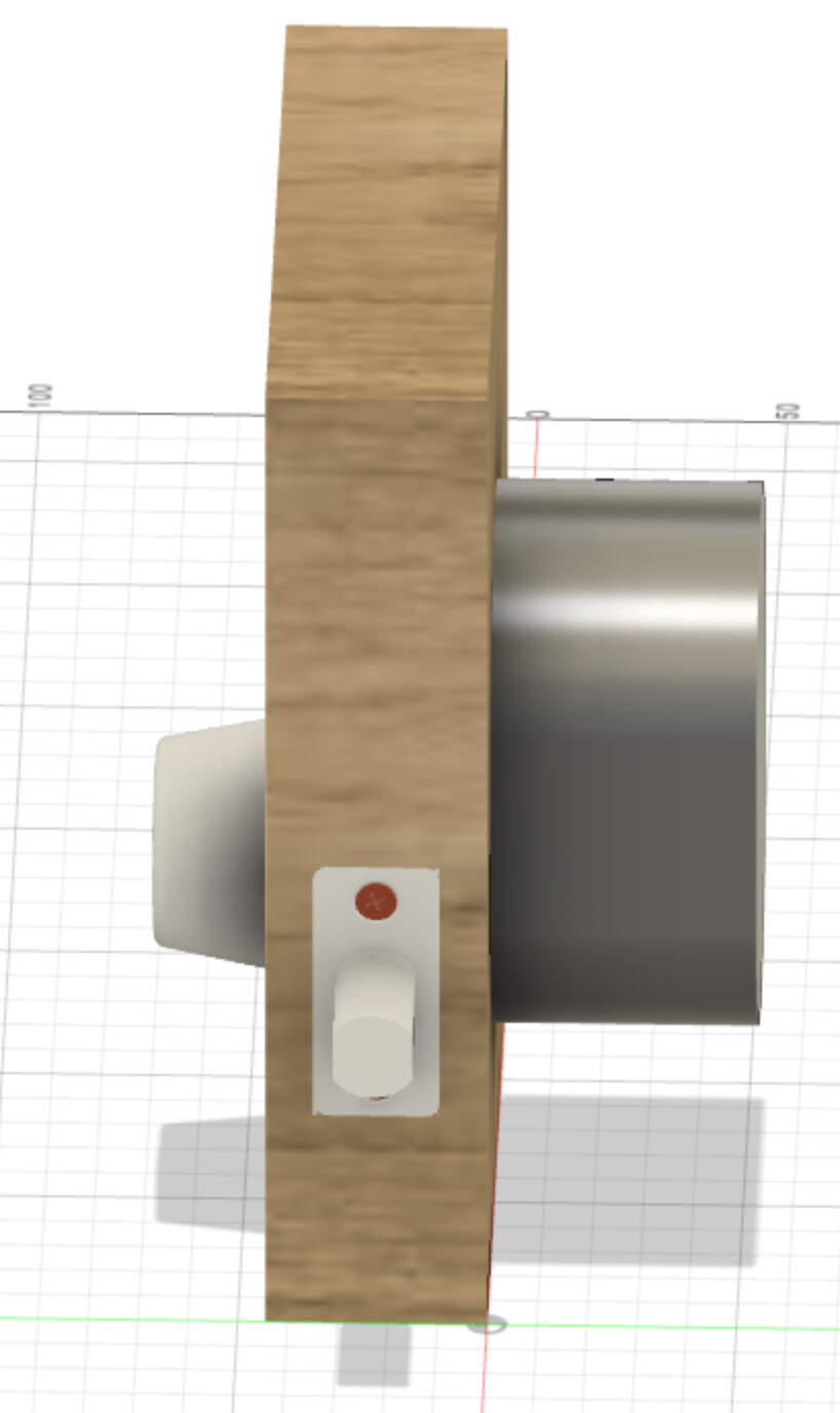
Side view showing how thick the back of the lock would be if we stand that DS3218 right into the lock shaft.
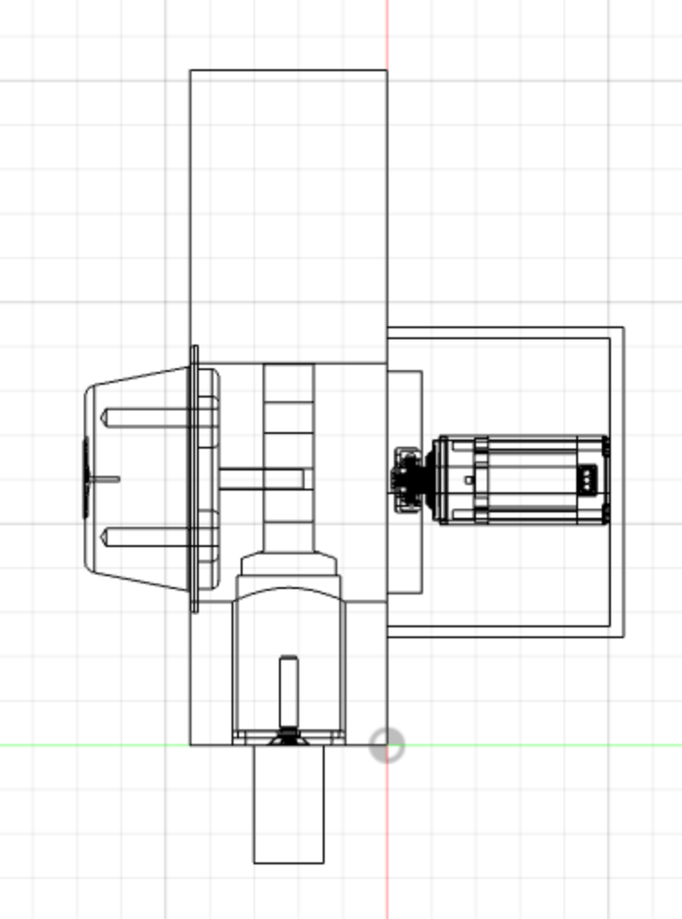
x-ray view of the side
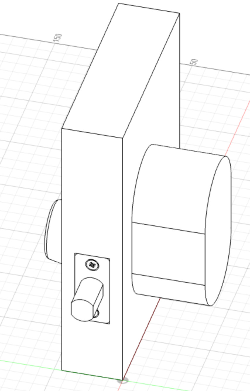
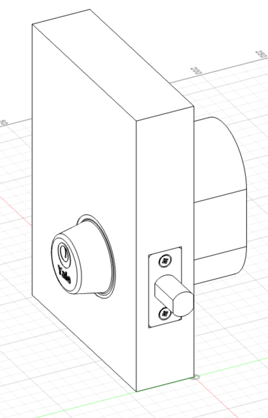
this doesn’t have a reader on the front, or any real locations for stuff except for the servo and the normal lock stuff. But at least I have all the parts that we can mess with now.
1 Like
Wow, looks great. I may have a solution to the wires thing. use wires, but instead of going around the door go through the original hole. I was thinking we could make a small spacer for the front portion of the lock that acts as a mount for the reader and allows room for the wires to pass through.
My thought on this is to not have wires at all, but instead create a wireless interface for a separate unit to do the reading and relaying card reads to the inside unit. The power level would need to be very low because it’s only going a few feet at most, and the radio link need not be secure either because the reader link would be treated as hostile (as it should). Of course this assumes only secure cards be used, like VivoKey or similar secure chip cards. The GIMDOW lock approach is what I’m basing this concept off of, where they have a separate keypad that communicates this way… though I don’t know if it’s secure or not.
Bluetooth 5.3 has a great stack for this regardless, and the BLE 5.3 security model has been proven fairly robust. It could enable phone comms and NFC reader comms both.
The most important element in my opinion is the mechanics on the back side of the door. I really want to figure out a way to work a low cost, extremely flexible and adaptable mechanical thumb turn interface. Something that is very forgiving and can self-adjust to the basic design of most any thumb turn… the classic T shape. I was envisioning a system that kind of worked like a spring loaded phone gripper;

Making this work and work well is going to be the hardest thing, but I really believe it’s the best way forward because there are just too many different types of bolts, locks, latches, etc. for tons of different types of doors all over the world… as well as rules for apartment dwellers on alterations… but they all have a thumb turn that is nearly identical in design.

Just my 2 cents.
2 Likes
My main concern with this is complexity with the software. It creates a lot of room for errors. I could see an issue of trying to get consistent communication between the devices, and if that connection fails, how difficult will it be to get them to reconnect on their own? In my experience with Arduino ide at least, is when something goes wrong it needs a hard reset(like power down, or re-uploading code, usually the reset button hasn’t been enough) before things will work normally.
How would an implementation like that look? I would want it to work with the spark 2 if that’s the case; since there’s not a huge list of use cases for it right now.
Could you elaborate for a newb in security ![]()
Also just a thought, what if we used a garage door type setup for communication between the readers. Reader validates key, sends radio signal to lock telling it to open. Since you have to program the remote to the garage door opener, card reader and door lock in our case, it would be a mildly secure connection(someone could still steal your remote code with a flipper or something similar, but you can do that to any house with a garage also…)
Issue with sperated reader/lock is then you have 2 batteries to worry about and monitor.
Basically for spark 2 / vivokey, the lock would have a secure element inside which would communicate via bluetooth to phone through vivokey app to get a symmetric key for the spark 2 being registered and it would store this key inside the secure element inside the lock. for public key devices like apex and possibly even yubikeys with NFC or similar secure keys using fido/u2f it would just do standard challenge / response stuff and not need a connection to the vivokey backend.
the point of storing the spark 2 key in the secure element would be so only registration would require a connection to vivokey servers… after that it would operate autonomously and offline.
sure… here’s what i mean…
this is the exact thing we would not want to do because it treats the communication channel between reader and lock to be a fort knox of security, when it’s absolutely anything but secure. even “secure” communications are not necessarily always secure.
this has to do with the OSI layer… you can look that up but basically think of it like this… the rule of thumb is that you always treat the communication layer as hostile and vulnerable. in our case the nfc reader and the radio link between nfc reader and lock should never be trusted. instead, we ensure the lock inside passes a cryptographic challenge to the chip / card over the radio link, through nfc, and back again… the nature of this application layer data is cryptographically secured. if anyone tampers with or attempts to replay the data going between lock and chip, the cryptographic methodology we’re employing ensures those attempts will fail. we trust the security of the chip and lock to speak securely over insecure connections.
in short, if you wanted to just have the reader do the security part with the chip and then like… send a “it’s cool” signal to the lock, then anyone could easily read the “it’s cool” signal with like a flipper or similar device and just replay that signal to unlock the door. bad.
true, but seems like a very minor concern vs being able to actually use the lock on a door in an apartment complex where you’re not allowed to change door lock hardware. being able to actuate an existing door lock without having to alter or do anything to the door hardware itself is the path toward largest possible utility. there’s no way to know how the person’s door will be configured… the wire passthrough method won’t work on mortise locks which are extremely common in the EU… but you can easily use 3M removable adhesive tape to secure the lock body to the door overtop the thumb turn.
engineering for one retrofit solution vs 20 different types of door configurations is the best approach imho
1 Like
Thanks for the explanation. Now the question is how do we do it? Lol. I’m willing to help in every possible way I can, but this, especially the software, is way over my head.
Personally this started as an endeavor to get RFID at my apartment whatever way I could, even if it’s insecure since I’d be relying on security through obscurity…but now I want to do it right. At my work we have a sign on the wall that says “Do it right or do it again.” Only makes sense to apply it here too.
So, what’s our next step? Should we use Arduino ide or should we switch to Python? I have about the same amount of experience in both. But everything involving security is going to be completely fresh territory for me so I have no idea what’s going to work best for our use case.
The hardest thing is mechanical engineering the thumb turn interface. It’s got to be clever.