Open source deadbolt lock

I’m going to begin attempting a conversion of an August lock to RFID with an xACv2. I’d like to at some point build an Arduino based(or similar)smart lock from scratch. The main issue is my complete lack of 3D modeling skills. The plan was to use the august lock project as a learning experience for how I want electronics to operate. Then figure out a lock design later. If anyone wants to help with the 3d aspect of things be my guest. Eventually I will pour time into it, but it will be slow going and I will be learning as I go.

The main push for this project initially was cost, but with switchbot costing just below $150 USD, and if it works with NTAGs or the APEX then I may not waste the time. On the other hand with the open source lock it could be a more private option offering only RFID and doesn’t require an account with a third party for all the other features the switchbot offers. As I’m only interested in the RFID, compatibility with an apartment lock, and low external profile.

One question I have is what’s the lowest profile i can make the coil for LF or HF? Could I make it a
paintable sticker with coils laying more side by side rather than stacked on top of each other?

1 Like

It seems like the most common desire in this thread is a dead simple, RFID only, no internet, over-thumbturn (same as gimdow and switchbot) solution. A big benefit I see of using existing deadbolts is the addon stuff has almost no requirement to be sturdy (metal) anymore. As long as the external module just sends over the tag data and doesn’t do any validation, there shouldn’t be bad downsides to the external module being trivial to smash or access the internals of, right? (Of course there are some downsides, but on the “security by obscurity” debate I’m of the opinion that if what you want is something with comparable or better security to your actual lock, any deadbolt add on tag unlock system realistically already more than fulfills that, even if most of the electronics are on the outside of the door)

It would be cool if printing could be used for most mechanical parts (mostly the housings and electronics mounts, but from what I’ve seen, even printed things like gears can be surprisingly reliable) and COTS mechanical (heatset inserts bolts etc) and electrical parts bought in bulk by someone and sold soldered together in kits at cost + 20% or whatever. Maybe this project could finally push to a V1 if the lock design is taken care of by the door, and part manufacture mostly taken care of by the user (don’t have to worry about batch size). I’m assuming many people interested in this have access to a printer anyways and pre-assembled kits can be sold for those that don’t, or that don’t want to do the assembly process.

For a no-bells system, the only electronics needed should be a motor, two battery holders, two bluetooth chips, a LF antenna, a microcontroller, and some type of sensor(s) (two limit switches keeps it nice and simple and cheap). is there anything expensive I’m missing there? If not, I can’t see that BOM running more than $50 or so, although I’m not very most familiar with prices of this kind of stuff. Plus maybe $20 for all the non-printed mechanical parts.

It seems to me like the thing most are looking for, at least on here, is a lot simpler than a) anything on the market that works with tags, and b) a lot of the options that have been looked into for open-source manufacture thus far. I personally don’t care about any internet integration, encrypted signals, deadbolt replacements, any tag other than RFID, etc. The only “extra” features I can see being useful to me (and presumably others wanting a simple and relatively cheap add in type thing) are notification of low battery and confirmation of locking, both could be done with an outside-facing LED or beeper.

I’m also a fan of replacing the added-on thumb turn with a button to solve the problem of it being relatively difficult to turn by hand because of the relatively high torque motor (implemented a bit up-thread in the capstone project post, a version of which with better battery life would meet all my needs). Then you would only encounter the high torque when using an actual key, which doesn’t seem to be much of an inconvenience to me, as long as it is physically possible. Just give an RFID tag to anyone coming to your house a lot, the key is a backup.
2 Likes

Agreed, this is what I am looking for. My main concern in this venture is legal trouble with potentially copying a design and getting sued(such as having too similar of mechanism that turns the deadbolt). I have no idea how any of this works in terms of open source and patent laws etc. I don’t have any of the resources to deal with something like a lawsuit if it came down to it. I don’t want a keypad however. I’d like to figure out a solution where everything is mounted to the door through wires(just for the LF antenna), but no additional holes or permanent damage to the door.

I agree. Destruction of the hardware accessible from the outside will only destroy access through RFID (very inconvenient if an auto lock feature is implemented and the RFID system fails). This implementation will be the equivalent security of the systems the xEM is compatible with. Meaning that if someone is close enough to your RFID chip with something like a flipper they can get access to anywhere that chip is registered to…like your RFID deadbolt. So yes as long as obscurity through obscurity remains intact your lock remains the Same level security. However, if that obscurity is broken then it’s potentially easier to steal your RFID UID than it would be to pick your lock or duplicate your physical deadbolt key. I’m not looking for additional security, just a keyless entry method that doesn’t change the deadbolt lock, and only the LF antenna on the outside of the door as I’m in an apartment complex that requires approval for modifications and I can’t be bothered.

The system I have in mind would implement the xAC available on the dangerous things website. It runs on 12v(although I think it can run on 9v according the documentation that came with it). I believe it draws 40mah on idle with operating being a bit higher. 3 18650 in series will give you 12.6v fully charged, dropping to 3.7v on the low end. They have a capacity up to 3200mah, 2 sets of 3-18650(in series) in parallel with each other would give about a week worth of battery. 21700s have the same voltage but up to 5000mah each so it would give you a couple more days. Or we could implement a power on switch to mitigate that.

I have more to say but I must go to bed. I’ll reply more later today.

While it would be nice to get a premade solution for both the chip reader and microcontroller, that 60 mA is a real killer. Changing out 6 18650’s every week isn’t reasonable for long-term use. There is no reason something like this has to draw nearly 60 mA. Going with electronics other than the XAC lets something like this last a lot longer (I guess the XAC is mostly intended for projects where power draw isn’t one of the main considerations).

Using the XAC also limits you to wires. Instead, I think that two entirely disconnected modules would have some benefits. It does mean twice the batteries every replacement, but I’m hoping that won’t be that big of a deal if it’s only changing out a few AA’s every few months. But in return, you don’t have to figure out how to run a wire to the second module, and in fact can mount it anywhere you want. I’ve seen some complaints that it is cumbersome touching implants to readers on doors depending on the door positioning, so having no positioning requirement for the outer module could be useful with ergonomics. You could even carry the second part around with you if you wanted to. There doesn’t seem to be any lack of cheap wireless transmitters, and it’s not like you need anything but the most basic data-transfer speeds for this application.

I don’t think the copyright thing would be much of a problem… I mean, it’s trivial to make an adapter that grips a knob decently that a motor turns. I don’t even know if you could get sued if you copied the exact mechanism from a company, there’s only so many ways to approach some problems, but there’s no need to copy an existing design exactly.

What microprocessors do you have in mind that draw less mah? Arduino uno draws 42mah base no sensors with a minimum operating voltage of 7v

An ARM Cortex M0 would be a good fit. It has a variety of low power modes and would perform better than something you’d find in an Arduino like an Atmega328.

Check out the Adafruit Trinket M0

You could run the whole thing off of replaceable CR123 batteries (probably two because any motor worth it’s salt will require that 6V or more). They have a staggeringly high energy density for the size. 32 x 16mm and 1500mAh

1 Like

Correct me if I’m wrong, but that sounds like NDEF, and I thought you couldn’t load NDEF on a mifare?

Maybe it will accept an ntag or other 14443a

1 Like

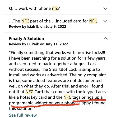
That’s referring to NFC tag you stick near your door and it’ll run a program on your phone to unlock the door. It’s not using nfc purely to unlock the door, just using nfc to get it started

It looks like with a couple modifications you can get down to the microamp range pretty easily with a M0 trinket (different voltage trinket but still): Lowering the Pro Trinket Current Draw - adafruit industries

But, like they say in that thread, the real way to reduce power here is ditching the breakout board and all of its unnecessary features, which gets you sub-microamp without too much trouble. At that point I’d guess that how often you use the system starts to become the main determinant of its battery life. At 30 uA (achievable with breakout board as per above thread), and if each open/close uses 1 A for 3s (ballpark), assuming 1 AA is 4 Wh and you have 4 of them, that’s 10 years if you never open/close the door, and around 3000 open/closes assuming zero idle draw, so if you use your door more than once a day that’s already a bigger contributor than the idle draw.

1 Like

You can but that’s not an NFC compatible chip so not all phones support it.

Alright then I’ll get to work on the trinket. Already got one ordered. While I await it’s arrival I’ll continue learning ardruino ide and start getting the circuitry figured out…unless you think python will be better. I have a bit morel python understanding, but Arduino ide already has a library built for the rc522 13.56MHz module which is only $10 vs the PN532 that is $40

1 Like

The trinket m0 needs some rethinking. I’m new to this so I’m still learning all the products available. We need at least 10 digital pins and the m0 only has 5. 7 for the RFID 1 for servo control, 1 for optional door open/closed sensor of undetermined type yet, and 1 for an optional exit button.

I think this www.adafruit.com/product/5611 will work in increasing I/o but I’m not sure, also everything we add increases power consumption. I doubt we can get things into the microamp range

The RC522 is also likely out of the question due to the fact that I have to use an external power supply to get it functioning

After more research the pn532 in going to be our best option. But I don’t think the trinket is going to be the best option. There’s other microcontrollers like the fire beetle esp32 that’s compatible with it. It’s deep sleep goes down to 10uA and on a forum someone got 10mA with Bluetooth on, not that we’ll need Bluetooth but that’s pretty impressive.

I mean checkout the RFID homeassistant thread NFC reader with Home Assistant - #141 by W-rabbit I could easily mod the PCB to go into a deadbolt and move a motor. I’ve actually done this before at my work. I use this same pn532, a esp32-s2, and a servo to lock and unlock my lab door all controlled via homeassistants tag system running in a docker container.

Esp-home also allows for deep sleep to run on very low power Deep Sleep Component — ESPHome could even use a magnet to trigger wake-up and turn on the reader if you wanted a very obscure and specific deadbolt that is very power efficient because it wouldn’t be scanning all the time.

Maybe use a ir photodiode / proximity sensor to detect an obstruction is near, could be a hand or arm etc. That would take a very low amperage to run, and then you could fire up the NFC circuits.

Could make a knob that you twist and uses a tilt sensor that turns the reader on. It’d last forever! But would add one more step. A touch sensor is probably best, maybe even just a button under the front cover so when you tap you also are pressing in the button.

The back side could be a solar panel…

1 Like

Small solar panels can give around 60mA, the esp 8266 in normal operation is 80mA and deep sleeps to 10mA meaning if you did it right a solar system could get the logic to run basically forever. You’d just need a battery to run the reader and motor. With a low number of daily reads/opens it could live forever. The extra 50mA could go into a battery. But that’s assuming full light.