Ok I’ll try to get all of the drawings done soon, how do you want me to send them?
I will change it to 4xAA batteries as that sounds like a better solution.
The way that I have designed it there are 4 injection moulded plastic parts (incl battery cover) one sheet metal fabricated part and one machined part (milled).
This is great news about the factory that can make them!
Use rechargable alkaline AA batteries inside. To have a fixed battery would mean you’d have to… plug it in? Are you gonna have a cord hanging on your door all day?
My problem with using 18650 batteries is that if one were to fail, you’d need to go out an buy another one possibly leaving the lock unusable, decent quality ones here can be upwards of 10 euro.
If you use rechargeable AA’s, you probably already have spare around the house you could swap in and then head to the shop to get replacements.
Agreed… otherwise you’re soldering on spring connectors to a PCB and having to get them to insert it into the plastic molded part that is all complex to make
in other news…
The prelim drawings were sent off to one factory for “first thoughts”… we’ll see what feedback they have.
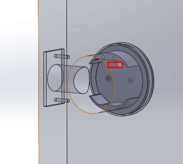
At first I was thinking we’d probably go with a flat ribbon cable and pin connector, so let’s make this round hole a long horizontal rectangle instead;
But, after thinking a bit… the difficult part here is keeping the reader chip on the inside with just the antenna bit on the outside. If we use a ribbon cable, it’s going to encounter some performance issues and possibly loss… but if we use shielded RG58 with maybe some other basic conductors running parallel, it’s going to be a thick unwieldy rope. I’m not sure which we should entertain just yet… @Satur9 let’s chat about this bit.
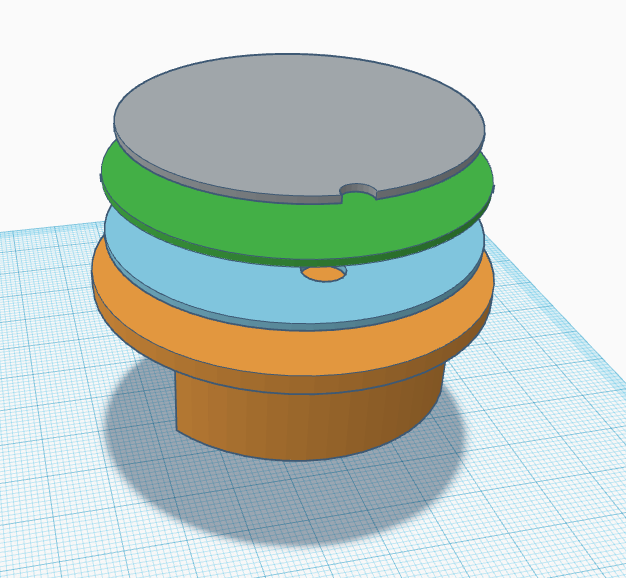
There are two ways to go with the antenna… make it part of the PCB as a trace antenna, or make it a wire antenna. For multiple reasons, I believe a wire antenna is the best way to go. Therefore, the outside antenna area of the lock will probably look something like this;
The blue disc is a 1mm this plastic or even a wax paper separator to keep the pcb from shorting… or we could use some other cheap insulator like conformal coat on the back of the PCB, but I trust a plastic disc more than anything.
The next disc is the PCB (classic green)… it will simply carry an LED (probably a simple red/green bi-color) and be an attachment point for wires and the antenna. The placement of the LED is not sorted yet so I’ve not bothered to put it in this simple drawing, but it would probably go somewhere toward the bottom of the PCB.
The grey disc is the ferrite polymer material. The antenna wire would connect to the PCB at the small notch at the top and it would lay on the ferrite polymer, probably glued down with some sort of simple adhesive sprayed on to the polymer.
missing bits
I didn’t bother to carry the holes through the various discs for securing the plastic cover overtop of all this.
I also purposely did not include anything to support the 9v battery terminals. I personally think this is not necessary, adds complexity and cost to the manufacturability of the mechanical design (sourcing pegs of the proper material, weatherproofing the connectors, etc.), and increases the depth (or height) of the external cover just to accommodate a battery connector. For the first design, I think the battery connectors should be omitted. Battery status can easily be conveyed to the user in a variety of ways, each increasing in annoyance, well before the batteries will actually drain past the point of functionality.
Sounds great, I may have to change the cable hole on the inside part of the door if the cable gets too big, there’s currently a gap of 3x8mm at the tightest point but I can probably find more space if needed.
With the led would a 3mm red/green one work, possibly on the Centreline towards the lower section of the cover?
I definitely agree with the choice to remove the battery terminals, they add far too many unnecessary processes for what you gain.
my thought was an SMT bicolor on the PCB and make the cover plastic two-toned or possibly just thinner in that section … or … ugh… a light pipe… but basically i don’t want the cover to have any holes in it… the light can shine through the face… thoughts? stupid? just put a hole you idiot? my primary goal is to keep it sleek and not have like a 1980s style LED poking out.
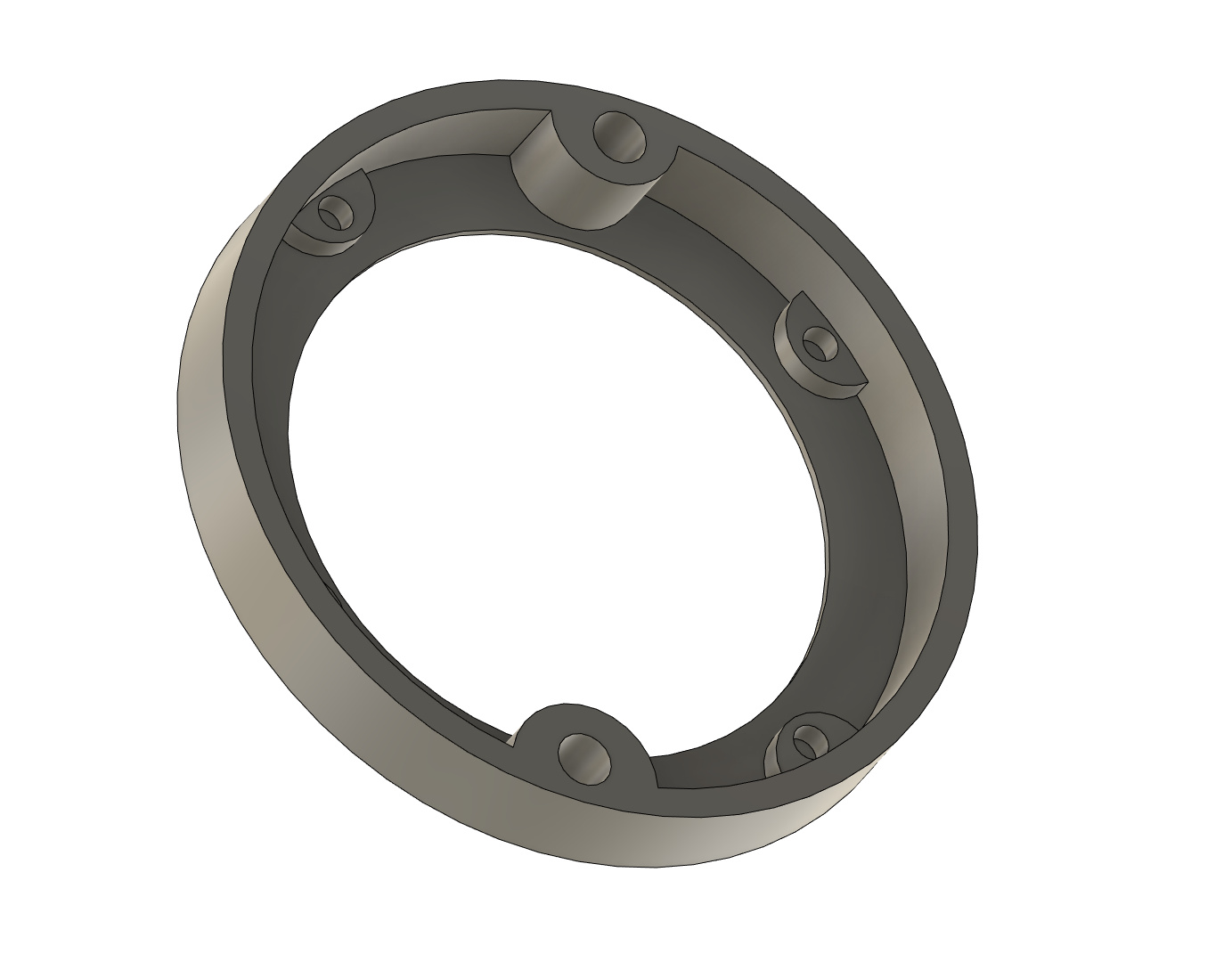
also any thoughts on making the inner diameter of the cover slightly smaller than the metal plate and then expanding a small skirt area around the edge so the plate fits into a kind of recess in the cover? just thinking about structural stability if someone smashes the cover hard… currently the only thing holding the cover is the two plastic pegs… but if the cover had a lip that the plate fit into, then it would kind of “seal” better and the cover would have support from outside force pushing into it… know what i mean?
Honestly we should not need to worry about shielded cables for the antenna, as long as the whole assembly is intended to stay enclosed within the lock body (no external patch antenna). As long as the wire or trace length is less than 1/4 the wavelength of the signal (λ = 22m for 13.56MHz signal) we shouldn’t have appreciable reflections. We’re talking about NFC (load modulation) here, so the antenna shouldn’t need to be shielded from ambient signals, and even if it does it’s blocked by steel on 5 sides.
What I would recommend is that the NFC antenna be formed on a polyimide flex PCB, which terminates in ENIG or hard gold contacts. Those can clip into a latching ribbon connector on the controller PCB. That ribbon can be threaded through a flat slot.
How about a clear insert / lens part that allows the light through and diffuses the light from the LED, similar to what Apple have done with the airpods and things?
The cover does currently sit just over the plate, not too sure what you’re asking? Like a lip inside the cover or something while keeping the shape?
I’m pretty sure you’re talking about a light pipe… a clear piece of plastic that extends through the otherwise opaque plastic housing. I think that’s possible but increases part count. If we can find a simple optically clear peg off the shelf, that’d be ideal over having to injection mold a tiny custom part… it’s got to be a super common kind of thing right? … Alibaba.com
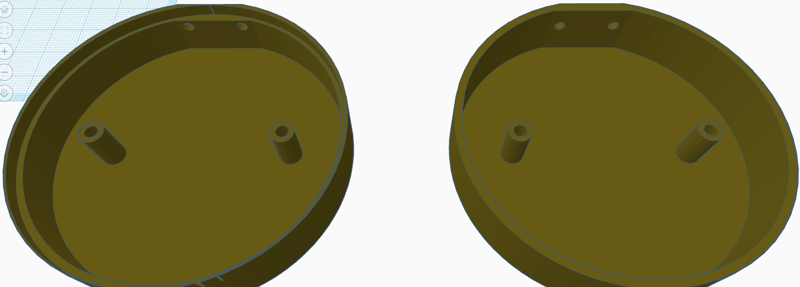
I was thinking much simpler… like this idea where the original cover is on the right and the cover with the lip is a little bigger diameter with a lip integrated so the plate fits into it;
I think if we get our materials for the plastic insulator, pcb, polymer, and wire antenna properly measured, the cover itself can hold things properly without too much pressure or need for an extra securing ring.
Again the only reason I’m thinking of this lip is that I want the cover to have more than just two screw pegs to stop outside force pushing the cover into the door… imagine someone “gently” punching the cover… some vandal or something… without the lip, those two pegs could break straight through the cover or deform the plastic at least, causing visible marks on the outside. The lip means the entire cover rests against the metal plate, not just sliding over it… so if someone were to punch or push on the cover, it would distribute the force around the entire circumference AND the screw pegs.