Just updated the drawings, I used the light pipe with part no LEM-135 from here:
1 Like
Ok I’ve started a bom file on the repo, but because i suck as markdown, it only makes sense when viewed in raw mode; https://raw.githubusercontent.com/VivoKey/lock-deadbolt/master/bom.md
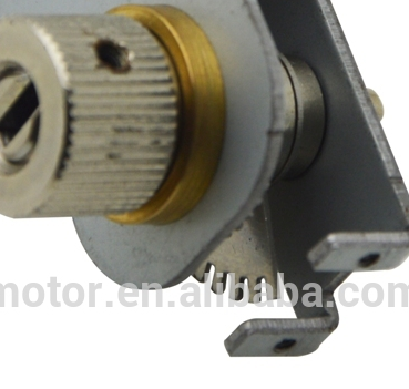
What do you think about this motor instead?
I really have no reason to suggest anything different from what you proposed, I simply like the look of this one more than the other… but that is a terrible basis on which to make any decisions… so looking for thoughts.
I’ve asked them to ship 10 samples to me. I will send you some once they arrive, just so you have a real-world idea of what they look like.
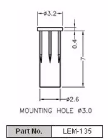
The “lip” on those is only 0.4mm thick, and I’m assuming the thickness of the plastic cover will be something closer to 1mm… so there might need to be a little seat or something to receive this light pipe “lip” into (similar to how the metal plate fits into the lip on the cover). I also noticed that this pipe has insert friction fins to hold it in place… so the lip of this pipe not actually fit nicely… we may need to have them mod the design or look at another similar option without fins. I prefer a nice solid fit into the cover with epoxy to hold and weatherproof it. But, this may not be a problem considering the drawing above… so we’ll find out exactly how well this part could work once we get the samples.
1 Like
@Satur9 not that I want to dive right into electronics design, but choosing a motor requires input from the EE side of things. When it comes to motor control and position detection, I assume that the bolt latch we’re using will fully stop at both rotational destinations (fully extended and fully retracted)… so how easy do you think it would be to do accurate current detection on the motor driver? I see 3 situations where the current would spike;
- bolt fully extended (locked)
- bolt fully retracted (unlocked)
- bolt jammed (not fully extended into the strike, but jammed on the strike plate or door frame)
Instead of position sensors for the motor shaft, we could instead use timing and current monitoring to detect state and position… but only if we are certain we can keep motor speed calibrated with voltage and current vs time. By that I mean, there are several scenarios that would greatly affect the amount of time it would take for a bolt to fully extend… so let’s examine the locking scenario;
-
new batteries, door strike is clear with no friction, bolt extends freely… time is 1 second exactly.
-
new batteries, standard latch is not fully in the strike (door not fully closed) creating friction for bolt extension, bolt extends under stress… time is 1.3 seconds.
-
half dead batteries, door strike is misaligned and standard latch is not caught creating a jam for the bolt (user must pull tension on door for bolt to align with strike), bolt extends and jams on strike… time to extend to jam state is 0.8 seconds with half dead batteries, but only 0.4 seconds with new batteries.
There are a bunch of scenarios where timing will change based on conditions but detecting the fully extended state vs a jam at the strike is critical since the lock will need to react differently to a jam vs full extension of the bolt. So using these made up examples above, the difference between a fully extended bolt with new batteries (1 second) and jammed bolt with half-dead batteries is only 0.2 seconds… and that margin could be eaten up easily by different door hanging scenarios where the gap between the door and frame is quite large, creating extra time to hit the strike in a jam scenario… so getting some method of calculating some kind of half-way accurate motor speed based on supply voltage and current draw, then using that speed as a weight for the timing calculations will likely be necessary.
The Samsung Ezon does a really good job of this kind of condition detection and resolution… and we will need to do this work as well.
1 Like
I’ll talk with my friend Dayo from InstaHub. I helped them with their design, and they overcame an identical problem.
1 Like
use a hall effect or optical sensor. The samsung lock uses two optical senors, one for open and one for closed. This is going to be way more reliable than timed.
1 Like
The issue with that motor is that it uses a worm drive gearbox making it impossible to drive by hand, i did try the in line version of that motor and it does generate the needed torque to turn the bolt, but only just at 6V. Mounting it was also an issue as its sooooo tiny!
The motor that I chose also has all of the drive couplings to actuate the lock in place already (flat bar & thumbturn on one spindle) it just made sense to me.
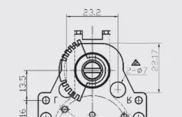
The plastic thickness is 3mm on the face and I have already altered the drawings to make this fit flush with the face.
I would probably epoxy it anyway just to make sure that it doesn’t move.
Can’t have them electronics getting wet and corroding now can we!
Brilliant, sounds good to me.
1 Like
I thought of that… didn’t notice exactly how that is done though… do they shoot over the flat bar in both directions or do they have something else completely?
Smart
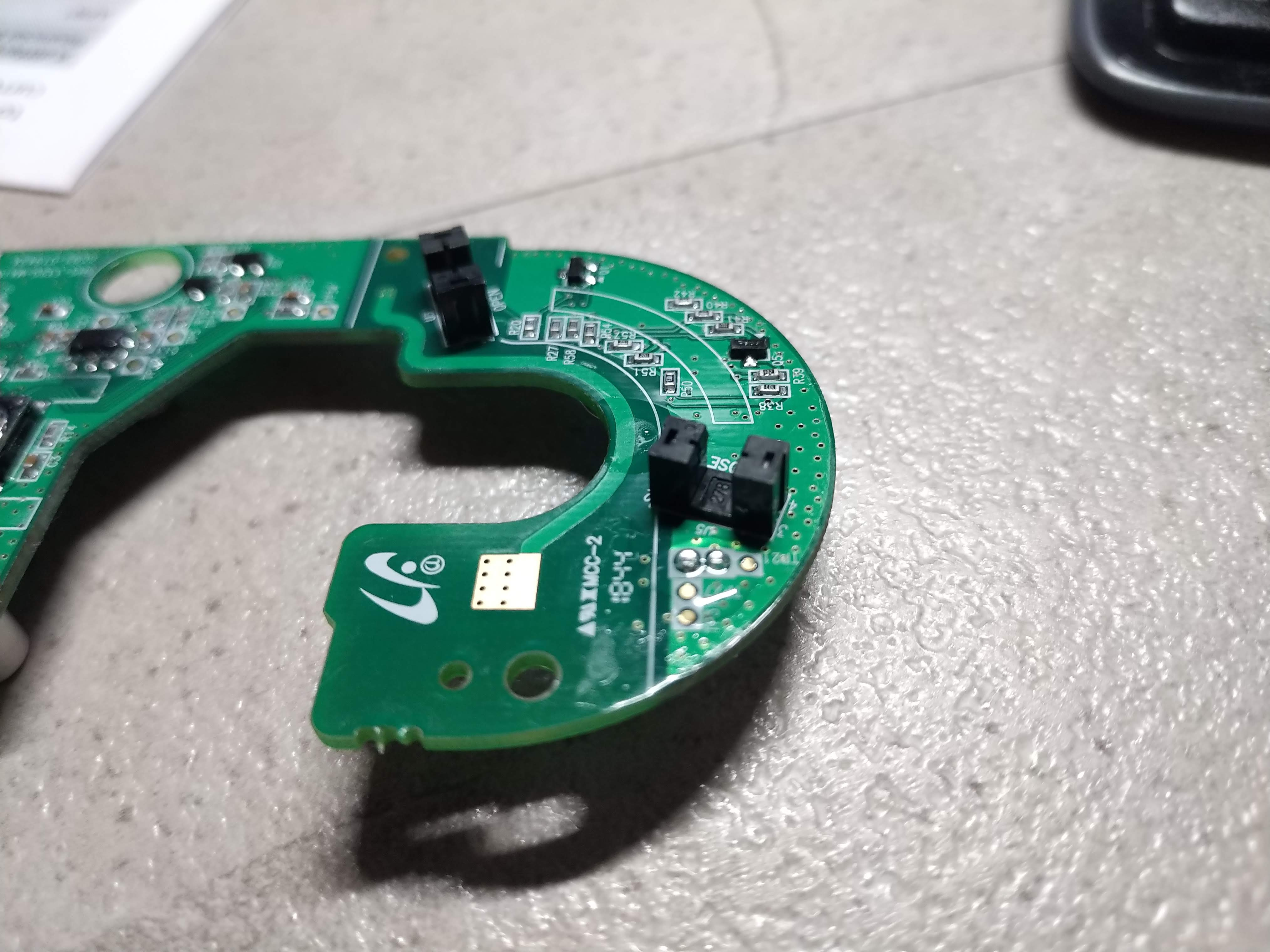
There’s a “flag” on the outer edge of the backside of the interior knob. The flag passes between optical sensors mounted on the PCB.
Their motor drives a gear around the interior knob, but the gear is a ring that floats. It has 180deg of play in relation to the position of the knob allowing you to lock and unlock it without backdriving the gearbox.
1 Like
That’s why the thumb turn is smooth like it is… interesting.
Clever. It’s probably smarter to emulate that design from a user-interface, reliability, and space-efficiency perspective than to drive the bolt directly. I could source some board mounted break-beam sensors.
Do you think you could post some pictures of this mechanism? Sounds like you have an open Ezon laying around ![]()
1 Like
also this? ![]()
![]()
![]()
We would still probably want some soft of basic current detection to look for bolt jams… or i guess we could just use timing the opposite way and assume if the bolt has been engaged for X milliseconds and we still don’t have input from the optical sensor, that the bolt must be jammed… a lot more slack in the timing thing if we do it that way.
I am requesting two samples of this motor… I’ll ship you one.
Well look at that… this thing seems to have some kind of fin that looks like it has notches for an optical encoder… it even looks like it has threaded mounts for the encoder too…
Not that we would use this necessarily, but maybe if we asked them to provide a fin or disc with holes that were 180 degrees from each other, but the holes were at different depths… distances from the center… radiuses?? … anyway, we could then mount an optical sensor block with emitter detector pairs at two different depths to determine which position the bolt was in based on the hole that lined up.
1 Like
Just FYI, DC current sensing on an SMT PCB is a painful design consideration. I’ve done it before.
Voltage detection can be done in parallel with the load, but DC current measurement has to be done in series with the load to get any level of accuracy (you could use a thermistor but accuracy is garbage). What people usually do is select an appropriately large (probably 3W in this case) but low value (~0.025Ω) surface mount resistor with a tight tolerance, and place it on the board edge near the motor connector with a voltage sense IC nearby to measure the drop. All the current that the motor sinks (including transient spikes) travels through the resistor for the current sensing to work. Over time, the value of the resistor begins to drift, which requires the firmware to have a recalibration protocol for a nebulous time period. Eventually the solder joint connecting the resistor to the board degrades and your load (motor) stops receiving consistent power and everything turns into a self reinforcing cascade of failures.
tl;dr

2 Likes
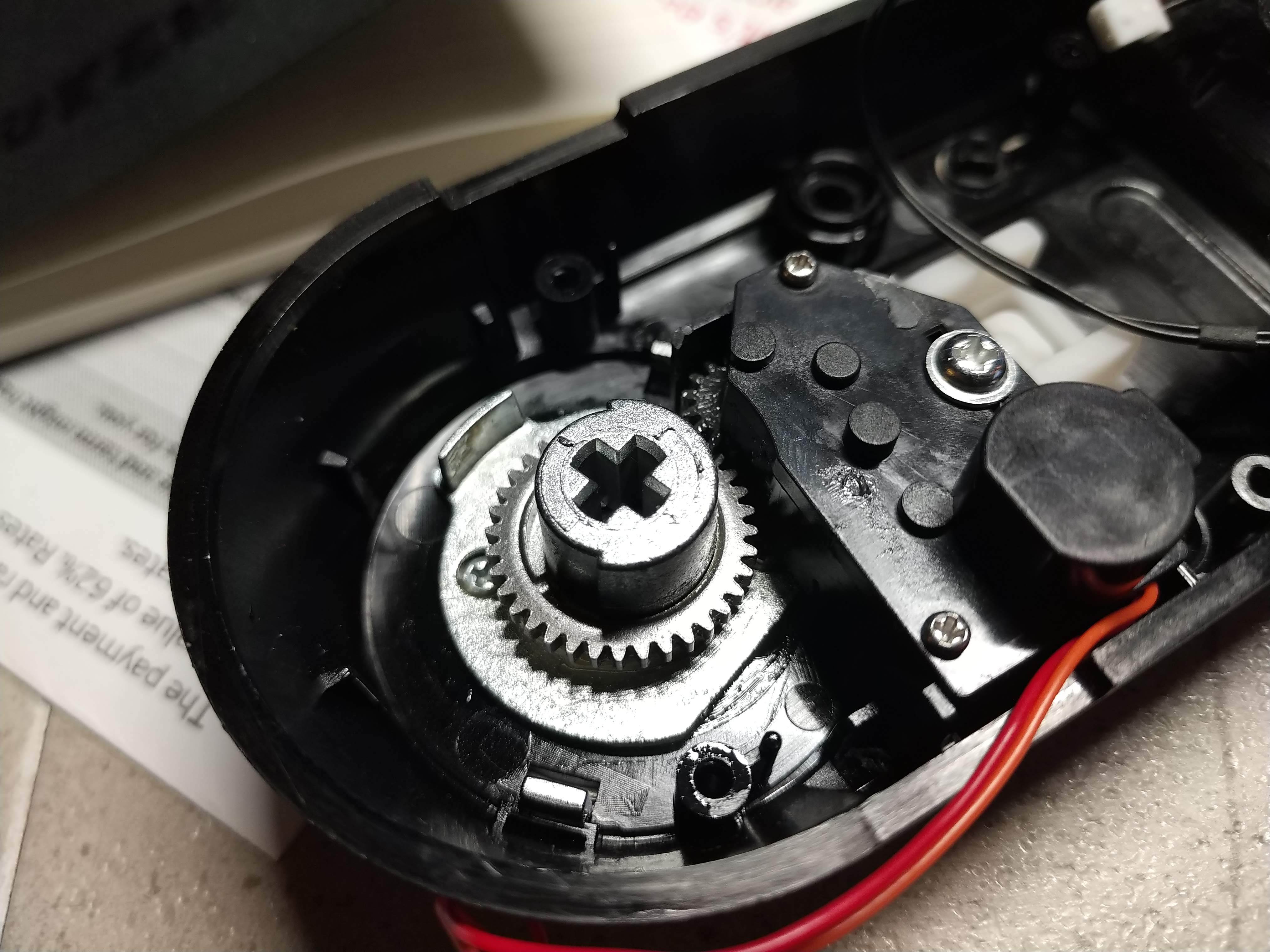
One position:
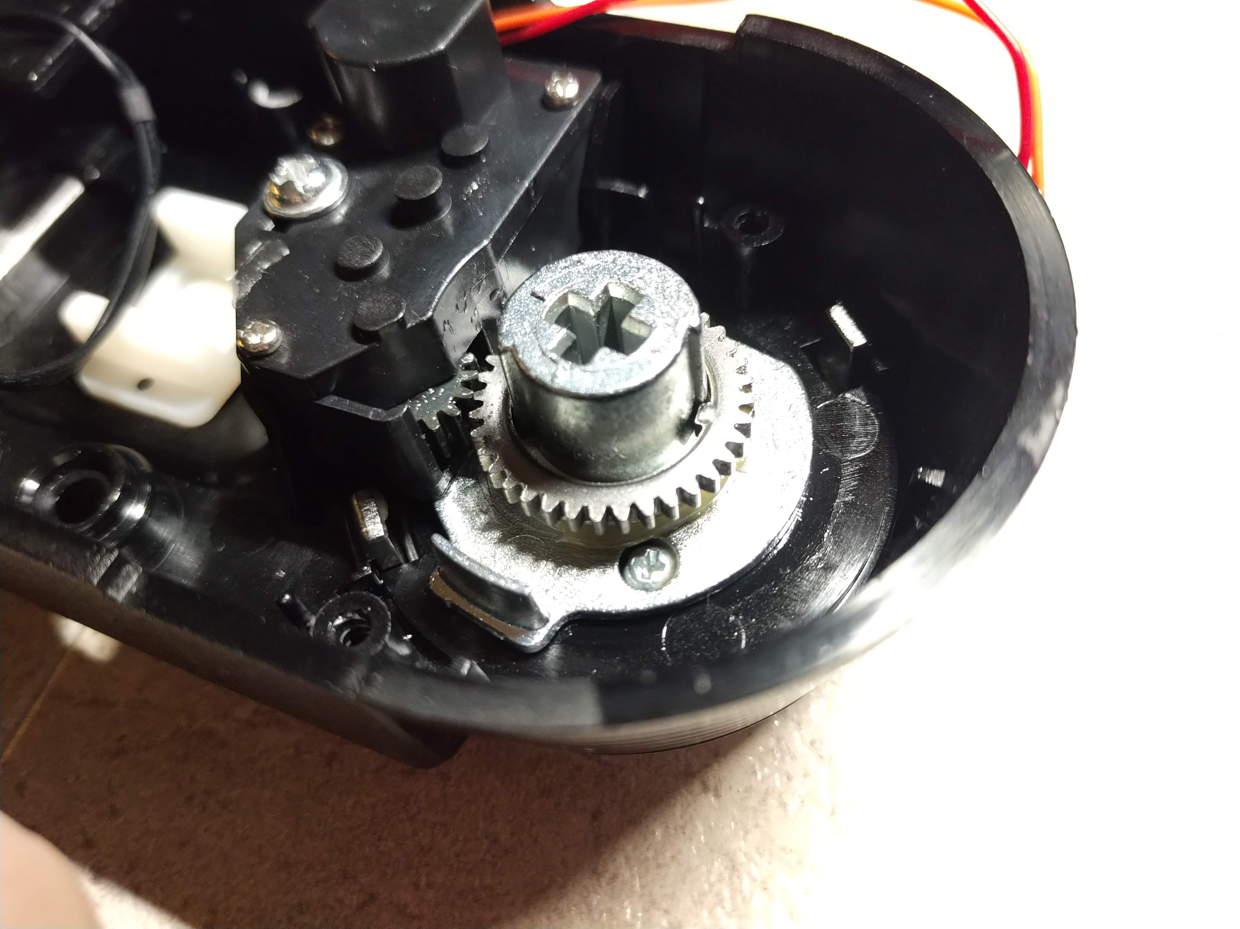
The Other position
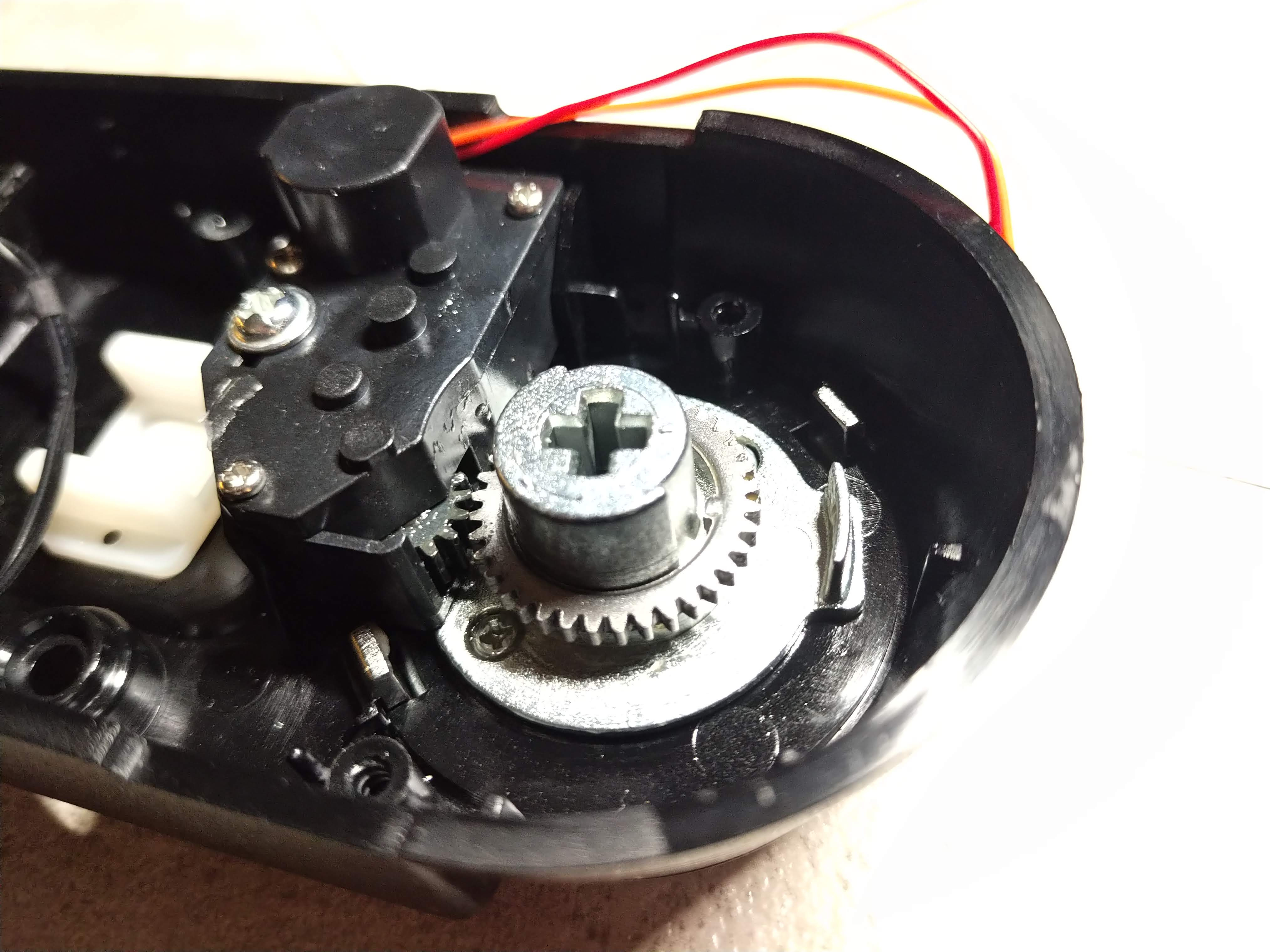
Note the ring gear did not move.
Optical sensors
The simplicity of this design is actually quite remarkable and I encourage those involved to chase after this level of simplicity.
This design could be used with a standard US deadbolt , meaning the outside plate could use a standard cylinder for backup along with a housing that provides an area for the reader… I understand some people might not want that so you have a model with a different front panel without the spot for the cylinder. The insides stays the same.
It should be designed to bolt through the door with the standard two screws.
1 Like
Using that it should be possible to know the position of the bolt at all times as it only has to rotate 90 degrees to lock/unlock and that can be done by counting the pulses right? and if there are 2 gates for the disc to pass through both will either be closed or open at the end positions.
Looking at the images it looks like the ring moved once when it was turned and then stayed in that position. From what I can see the motor will drive the gear wheel until it touches the lip on the thumbturn and then drive it open or closed a further 90 degrees. If then the thumbturn is turned manually it will still backdrive the gearbox.
It’s possible that I’m wrong but even so

Edit: upon further research the floating ring only seems necessary if a key lock is being used.
2 Likes
It makes the thumb turn also move freely without drag from the motor. It’s ingenious but I’m willing to skip it and go direct drive for v1. Lower part count = lower cost tooling
1 Like
Regarding backup power - a nice feature I saw on a smart lock recently is a micro USB port on the bottom (maybe USBC more trendy now?) instead of the 9v battery terminals. Thought process being much more likely you’ll have a battery bank and cable than a 9v battery. Not used for charging, just emergency power
USB-C connectors are still pretty expensive compared to a ready-made mold for holding AA batteries