Hello,
I’m trying to get a PN5180 to work but I seem to be missing something …
It’s 3.3v, so I’m experimenting with the ESP32 board to avoid the logic converters.
Anyone managed to make it work or has a code they’d be willing to share?
Thanks,
X
Hello,
I’m trying to get a PN5180 to work but I seem to be missing something …
It’s 3.3v, so I’m experimenting with the ESP32 board to avoid the logic converters.
Anyone managed to make it work or has a code they’d be willing to share?
Thanks,
X
dam, i was hoping someone had been able to get one up and running …
Will have to revert back to pn532 for my projects.
I’ve ordered some PN5180, but due to Chinese newyear’s it’s going to be a while. I’ll let you know when I have some code to share.
That would be awesome!
I’ve spent a few weeks trying to get them to run, but I don’t have anything …
Just popped in my head … Maybe I have a DOA board … But I would point finger to the code first …
I found some notes online about having to set some undocumented settings. But I can’t remember where. I will see if I can find them again.
Thanks all for looking out, I can do hardware all day long, but software always been my week point …
Starting to dig into the ESP32 and realizing it’s an awesome platform! It’s probably gonna get a permanent spot on the bench.
Are you using spi? you man need to fiddle with the clock rate like the pn532.
I’m not sure how to do that …
(I did said I suck at programming right? ![]() )
)
I need to try it again and post in more details what I do and how it doesn’t work …
Are you using SPI?
What library are you using?
Spi on the ESP32.
I tried 2 codes from GitHub with no luck.
Both seam to call out the same (installed) library called “PN5180.h”
The one I got the farthest has “andras trappmann” in the header of the code …
In pn5180.cpp
PN5180_SPI_SETTINGS = SPISettings(7000000, MSBFIRST, SPI_MODE0);
Try adjusting 7000000 to a smaller number try taking a 0 off it.
Ok, found it ![]()
Can I edit it with note++?
I’ll give it a go and see if it works
Well … I got 1 step further, the setup portion of the program seem to run through, the serial monitor said it’s started up properly ![]()
But I’m still not reading anything ![]()
I’ll try an idea tomorrow but I’m not too hopeful it will work …
PS: it’s not even reading the board, I can’t get the product version to talk back to me ![]()
Got my PN5180 today, and man, this board is impressive. Range is not even in the same ballpark as any other tested. And I have now tested quite a few. Best so far is about 0.5 cm from antenna to my implanted NExT.
This board can read my NExt at 2 cm! Didn’t even know it was possible, must be some radioactive stuff in this one. So far I’ve only tested using some stupid example code and reading UID. I suspect range will drop a bit reading NDEF and such, but it will be a fun challenge porting my keyboard wedge to this board.
Hi, I was having the same issue as well. I googled quite some time and found a method that will prompt response on your arduino serial monitor. Try to connect both 5v and 3v pin header at 3.3v
Where’s everyone buying theirs from? I could only find one on amazon, but I don’t know if I trust it. Found a bigger one on digikey, but it’s super big and bulky. Don’t think it’s the one everyone’s getting
Sounds awesome!
Do you have sample code and wiring diagram (or pic)?
I spent so much time trying to get it to work … I’d love to see how you made it
Got mine on Amazon … Seemed as good as any …
Amazon has burned me a few times when buying Arduino related stuff. Got a fake PN532 from them. So I’m a little wary nowadays haha
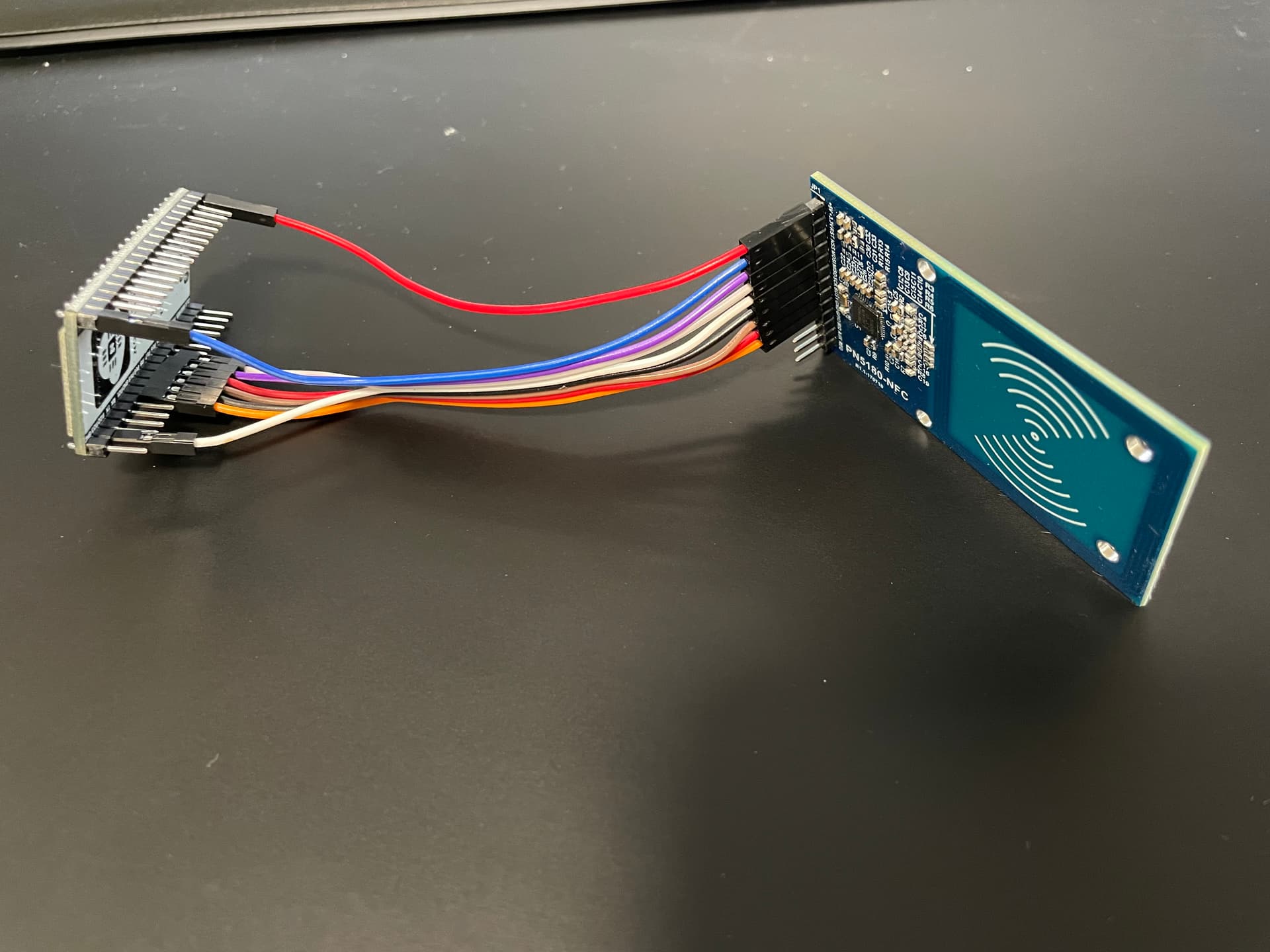
Test setup is not much to look at:
Remember that even though the library says 5v is not needed on ESP32, at least mine will not power the antenna without it.
Test code I found is even worse, but it reads UID:
// NAME: PN5180-ISO14443.ino
//
// DESC: Example usage of the PN5180 library for the PN5180-NFC Module
//       from NXP Semiconductors.
//
// Copyright (c) 2018 by Andreas Trappmann. All rights reserved.
// Copyright (c) 2019 by Dirk Carstensen.
//
// This file is part of the PN5180 library for the Arduino environment.
//
// This library is free software; you can redistribute it and/or
// modify it under the terms of the GNU Lesser General Public
// License as published by the Free Software Foundation; either
// version 2.1 of the License, or (at your option) any later version.
//
// This library is distributed in the hope that it will be useful,
// but WITHOUT ANY WARRANTY; without even the implied warranty of
// MERCHANTABILITY or FITNESS FOR A PARTICULAR PURPOSE. See the GNU
// Lesser General Public License for more details.
//
// BEWARE: SPI with an Arduino to a PN5180 module has to be at a level of 3.3V
// use of logic-level converters from 5V->3.3V is absolutly neccessary
// on most Arduinos for all input pins of PN5180!
// If used with an ESP-32, there is no need for a logic-level converter, since
// it operates on 3.3V already.
//
// Arduino <-> Level Converter <-> PN5180 pin mapping:
// 5V             <-->             5V
// 3.3V           <-->             3.3V
// GND            <-->             GND
// 5V      <-> HV
// GND     <-> GND (HV)
//             LV              <-> 3.3V
//             GND (LV)        <-> GND
// SCLK,13 <-> HV1 - LV1       --> SCLK
// MISO,12        <---         <-- MISO
// MOSI,11 <-> HV3 - LV3       --> MOSI
// SS,10   <-> HV4 - LV4       --> NSS (=Not SS -> active LOW)
// BUSY,9         <---             BUSY
// Reset,7 <-> HV2 - LV2       --> RST
//
// ESP-32    <--> PN5180 pin mapping:
// 3.3V      <--> 3.3V
// GND       <--> GND
// SCLK, 18   --> SCLK
// MISO, 19  <--  MISO
// MOSI, 23   --> MOSI
// SS, 16     --> NSS (=Not SS -> active LOW)
// BUSY, 5   <--  BUSY
// Reset, 17  --> RST
//

/*
 * Pins on ICODE2 Reader Writer:
 *
 *   ICODE2   |     PN5180
 * pin  label | pin  I/O  name
 * 1    +5V
 * 2    +3,3V
 * 3    RST     10   I    RESET_N (low active)
 * 4    NSS     1    I    SPI NSS
 * 5    MOSI    3    I    SPI MOSI
 * 6    MISO    5    O    SPI MISO
 * 7    SCK     7    I    SPI Clock
 * 8    BUSY    8    O    Busy Signal
 * 9    GND     9  Supply VSS - Ground
 * 10   GPIO    38   O    GPO1 - Control for external DC/DC
 * 11   IRQ     39   O    IRQ
 * 12   AUX     40   O    AUX1 - Analog/Digital test signal
 * 13   REQ     2?  I/O   AUX2 - Analog test bus or download
 *
 */

//#define WRITE_ENABLED 1

#include <PN5180.h>
#include <PN5180ISO14443.h>

//#if defined(ARDUINO_AVR_UNO) || defined(ARDUINO_AVR_MEGA2560) || defined(ARDUINO_AVR_NANO)

//#define PN5180_NSS  10
//#define PN5180_BUSY 9
//#define PN5180_RST  7

//#elif defined(ARDUINO_ARCH_ESP32)

#define PN5180_NSS  16   // swapped with BUSY
#define PN5180_BUSY 5  // swapped with NSS
#define PN5180_RST  17

//#else
//#error Please define your pinout here!
//#endif

PN5180ISO14443 nfc(PN5180_NSS, PN5180_BUSY, PN5180_RST);

void setup() {
  Serial.begin(115200);
  Serial.println(F("=================================="));
  Serial.println(F("Uploaded: " __DATE__ " " __TIME__));
  Serial.println(F("PN5180 ISO14443 Demo Sketch"));

  nfc.begin();

  Serial.println(F("----------------------------------"));
  Serial.println(F("PN5180 Hard-Reset..."));
  nfc.reset();

  Serial.println(F("----------------------------------"));
  Serial.println(F("Reading product version..."));
  uint8_t productVersion[2];
  nfc.readEEprom(PRODUCT_VERSION, productVersion, sizeof(productVersion));
  Serial.print(F("Product version="));
  Serial.print(productVersion[1]);
  Serial.print(".");
  Serial.println(productVersion[0]);

  if (0xff == productVersion[1]) { // if product version 255, the initialization failed
    Serial.println(F("Initialization failed!?"));
    Serial.println(F("Press reset to restart..."));
    Serial.flush();
    exit(-1); // halt
  }

  Serial.println(F("----------------------------------"));
  Serial.println(F("Reading firmware version..."));
  uint8_t firmwareVersion[2];
  nfc.readEEprom(FIRMWARE_VERSION, firmwareVersion, sizeof(firmwareVersion));
  Serial.print(F("Firmware version="));
  Serial.print(firmwareVersion[1]);
  Serial.print(".");
  Serial.println(firmwareVersion[0]);

  Serial.println(F("----------------------------------"));
  Serial.println(F("Reading EEPROM version..."));
  uint8_t eepromVersion[2];
  nfc.readEEprom(EEPROM_VERSION, eepromVersion, sizeof(eepromVersion));
  Serial.print(F("EEPROM version="));
  Serial.print(eepromVersion[1]);
  Serial.print(".");
  Serial.println(eepromVersion[0]);

  Serial.println(F("----------------------------------"));
  Serial.println(F("Enable RF field..."));
  nfc.setupRF();
}

uint32_t loopCnt = 0;
bool errorFlag = false;


// ISO 14443 loop
void loop() {
  if (errorFlag) {
    uint32_t irqStatus = nfc.getIRQStatus();
    showIRQStatus(irqStatus);

    if (0 == (RX_SOF_DET_IRQ_STAT & irqStatus)) { // no card detected
      Serial.println(F("*** No card detected!"));
    }

    nfc.reset();
    nfc.setupRF();

    errorFlag = false;
    delay(10);
  }
  Serial.println(F("----------------------------------"));
  Serial.print(F("Loop #"));
  Serial.println(loopCnt++);
  if (!nfc.isCardPresent()) {
    Serial.print(F("no card found"));
    return;
  }
  uint8_t uid[8];
  if (!nfc.readCardSerial(uid)) {
    Serial.print(F("Error in readCardSerial: "));
    errorFlag = true;
    return;
  }
  Serial.print(F("card serial successful, UID="));
  for (int i=0; i<8; i++) {
    Serial.print(uid[i], HEX);
    if (i < 2) Serial.print(":");
  }
  Serial.println();

  Serial.println(F("----------------------------------"));

  delay(1000);
}


void showIRQStatus(uint32_t irqStatus) {
  Serial.print(F("IRQ-Status 0x"));
  Serial.print(irqStatus, HEX);
  Serial.print(": [ ");
  if (irqStatus & (1<< 0)) Serial.print(F("RQ "));
  if (irqStatus & (1<< 1)) Serial.print(F("TX "));
  if (irqStatus & (1<< 2)) Serial.print(F("IDLE "));
  if (irqStatus & (1<< 3)) Serial.print(F("MODE_DETECTED "));
  if (irqStatus & (1<< 4)) Serial.print(F("CARD_ACTIVATED "));
  if (irqStatus & (1<< 5)) Serial.print(F("STATE_CHANGE "));
  if (irqStatus & (1<< 6)) Serial.print(F("RFOFF_DET "));
  if (irqStatus & (1<< 7)) Serial.print(F("RFON_DET "));
  if (irqStatus & (1<< 8)) Serial.print(F("TX_RFOFF "));
  if (irqStatus & (1<< 9)) Serial.print(F("TX_RFON "));
  if (irqStatus & (1<<10)) Serial.print(F("RF_ACTIVE_ERROR "));
  if (irqStatus & (1<<11)) Serial.print(F("TIMER0 "));
  if (irqStatus & (1<<12)) Serial.print(F("TIMER1 "));
  if (irqStatus & (1<<13)) Serial.print(F("TIMER2 "));
  if (irqStatus & (1<<14)) Serial.print(F("RX_SOF_DET "));
  if (irqStatus & (1<<15)) Serial.print(F("RX_SC_DET "));
  if (irqStatus & (1<<16)) Serial.print(F("TEMPSENS_ERROR "));
  if (irqStatus & (1<<17)) Serial.print(F("GENERAL_ERROR "));
  if (irqStatus & (1<<18)) Serial.print(F("HV_ERROR "));
  if (irqStatus & (1<<19)) Serial.print(F("LPCD "));
  Serial.println("]");
}
Code is for ISO14443A cards, not ISO15693
Ok, been messing with this for a few days and im not getting much closer …
I now get this message in a loop (fast) and cant figure out where it comes from …
and it doesnt seam to change when i present a tag …
rst:0x3 (SW_RESET),boot:0x13 (SPI_FAST_FLASH_BOOT)
configsip: 0, SPIWP:0xee
clk_drv:0x00,q_drv:0x00,d_drv:0x00,cs0_drv:0x00,hd_drv:0x00,wp_drv:0x00
mode:DIO, clock div:1
load:0x3fff0018,len:4
load:0x3fff001c,len:1044
load:0x40078000,len:10124
load:0x40080400,len:5856
entry 0x400806a8
ets Jun 8 2016 00:22:57
Any idea where im screwing up?