Right, Here it is, The project NOBODY has been waiting for ![]()
I have documented it just incase somebody cares…or want’s to make something similar.
What is it?
A gizmo that is cheap and simple for anybody to build, use, and read allowing you to accurately
measure the read range with any reader of your choice
Design idea and thought process
The design brief I gave myself was, ideally to :
-
Build it with mainly plastics and/or wood
-
Minimal metal
-
Accurate enough to millimeters
-
Capable of being reader agnostic
-
Metric
3D print ![]() ???
???
I did consider designing and printing this project all on a 3D printer, But I wrote that off due to time, effort and the reward, with the exception of some parts that I will build, to be discussed later.
The core purpose of this gizmo is to the need to measure, so what options do we have?
-
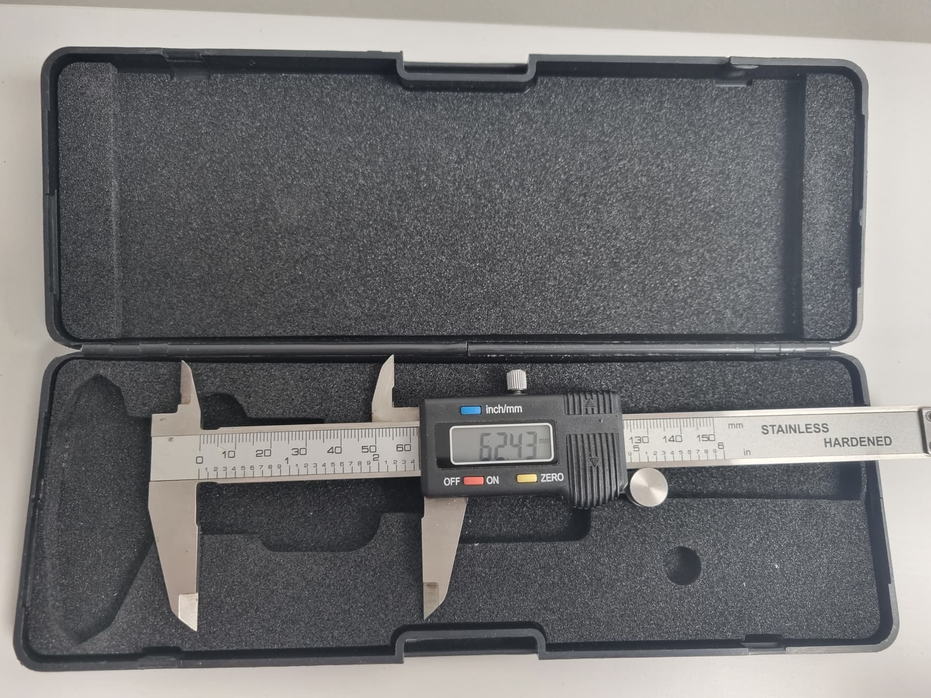
Digital calipers!?
They are super accurate, but the ones I had were metal which I would prefer to avoid
They would work, They are easy to read and very accurate, but I think we can do better -
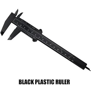
Plastic calipers!?
I do have some plastic ones similar to these
They are a pretty good option, But Again, I think we can do better
Long story short,
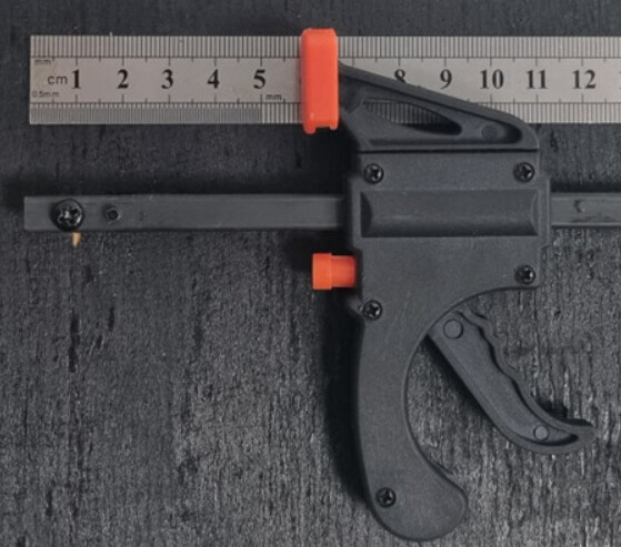
I went with this combination
Parts List
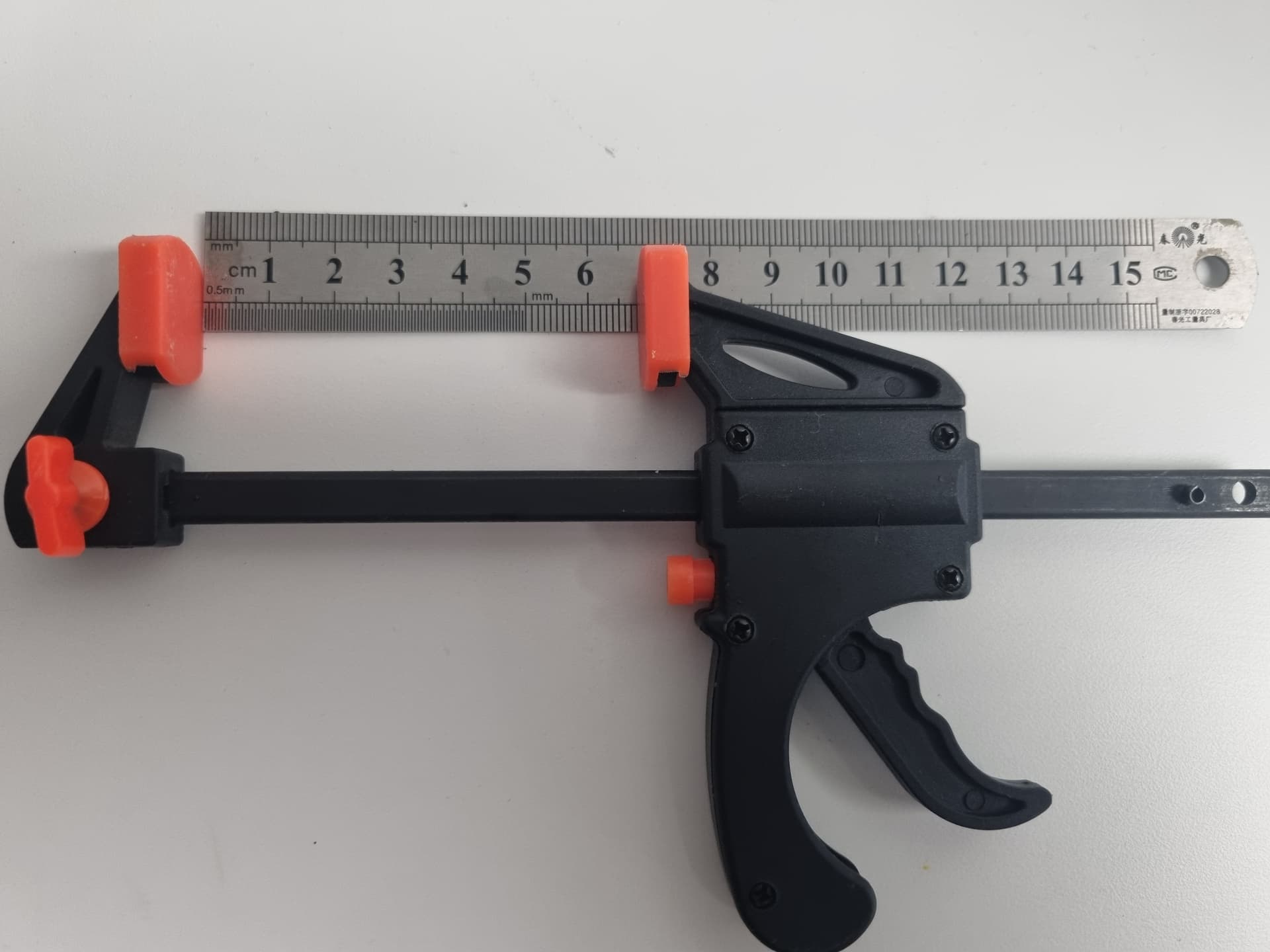
This gives me the accuracy I needed with the control I wanted, allowing one handed operation so I can hold my phone to record with the other hand if I chose to.
The ruler was metal, I could have gone plastic or PCB ruler, but this one was thin and at hand…
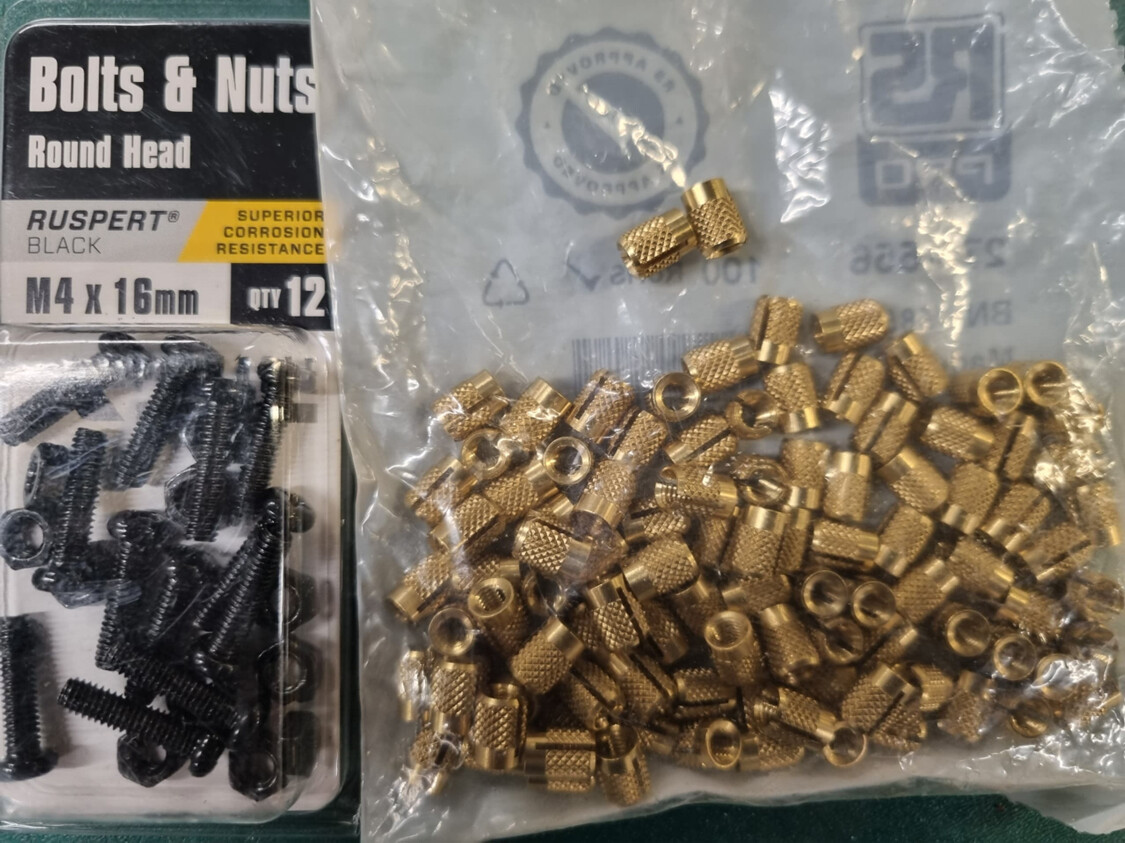
M4 x 16 nuts and bolts
4mm threaded inserts (5.5mm drilled holes)
You could just use screws!
The base is a scrap bit of plywood ~ 300mm x 150mm
Some Paint to make it purdy.
Layout
One decision point I had was ![]() “do I move the reader to the implant, or the implant to the reader?”
“do I move the reader to the implant, or the implant to the reader?”
I chose to have the Reader at zero and the implant at the moving end rather than the other way around.
Build
After the layout,
Mark where the holes go
Drill the holes 5.5mm
Insert the threaded inserts, tap them home with a small hammer ( or whatever is handy because EVERYTHING is a hammer if you need one)
Double sided tape on the back of the ruler
Place the ruler down and screw the bolt through the hole into the insert
Push the bolts through the clamp holes
Thread 2 nuts onto the bolts to act as a stand-off allowing the clamp to slide
Screw the clamp bolts into the threaded inserts
That’s it !!! Simple Pimple
Job’s a good’un
Size
I could have smallified the footprint, but I built it around the clamp and the ruler.
The ruler is 150mm+ but in reality, the realistic ranges of our implants/RFID cards etc. are <50mm
Anything >20mm is exceptional, so I could have made a very small test platform, but who wants a chode tool? ![]()
Accuracy
Although it’s measured to mm, visually it is easy to measure to .5mm
At the end of the day, I think 1mm is “Accurate enough” for implant purposes
What it looks like and how it works
Shes pretty rough, but It only took me about 10-15mins ( not counting paint drying time )
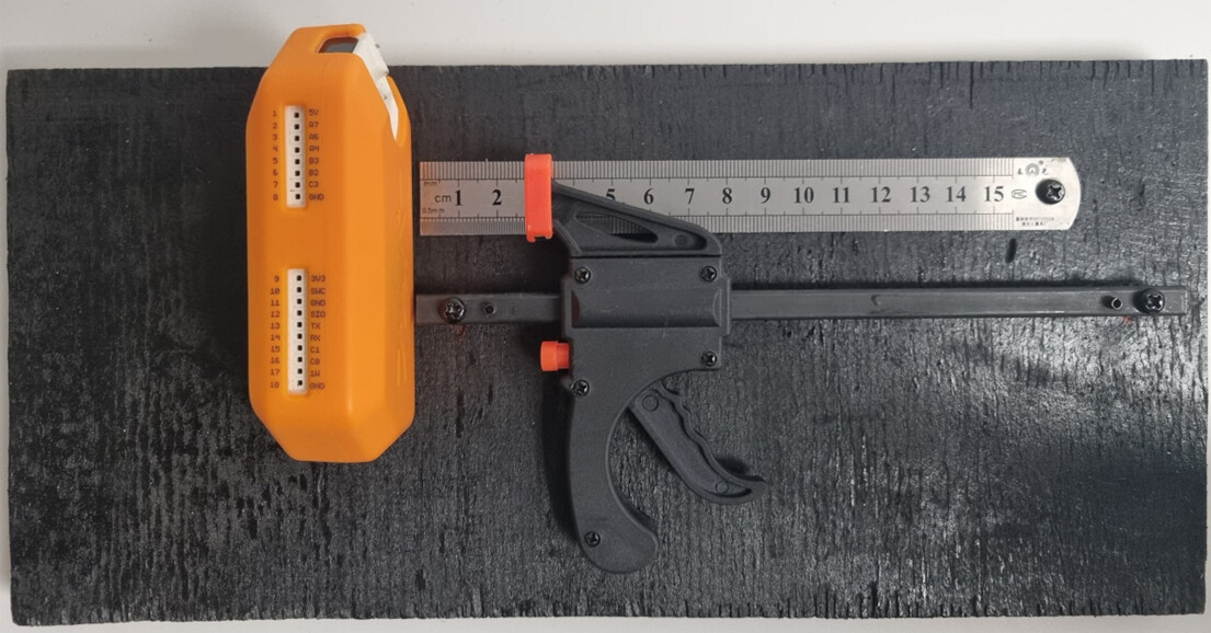
It works as simple as it looks
Place the reader of your choice at the zero end (Standing end)
mount the implant at the measured end ( Working end ) - taped on until I make the caddy.
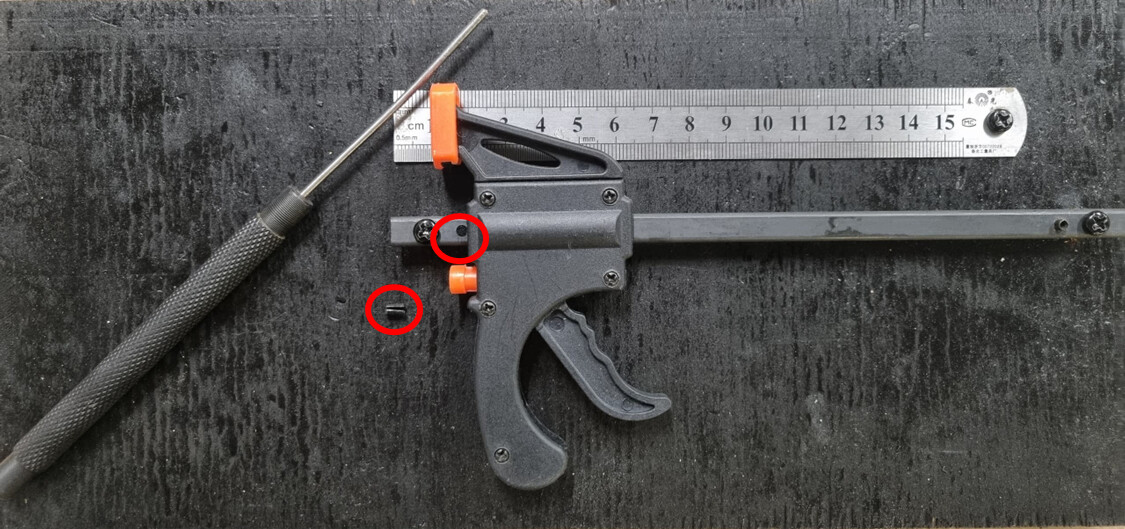
Squeeze the clamp trigger and the implant moves toward the reader, one full squeeze moves the implant ~2.5mm, you can control how far it moves by how deep the trigger is squeezed.
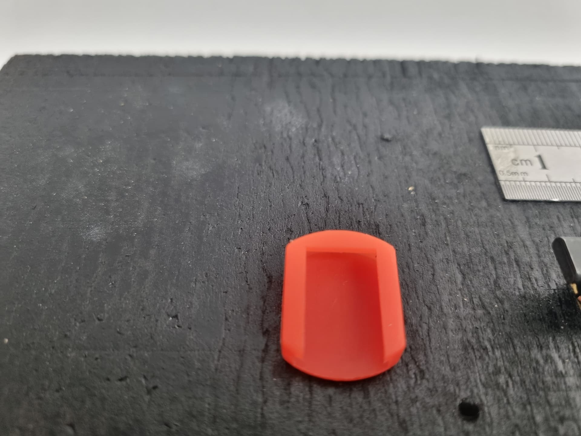
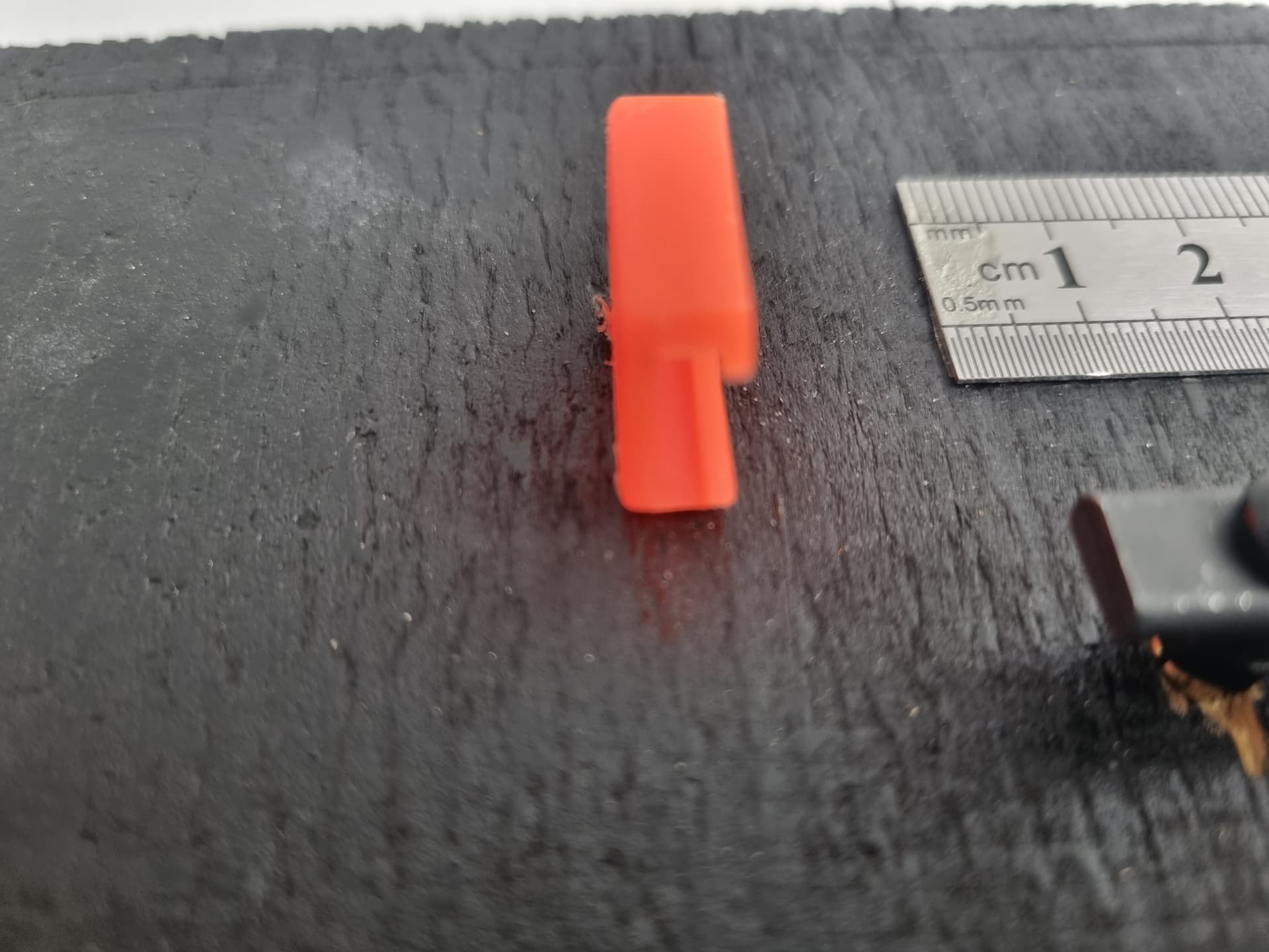
You can release / reset the implant end with the little orange button
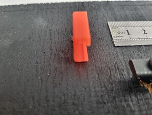
There was a little “gotcha”, in the form of a pin that stopped the implant from getting any closer than 10mm to there reader, and as most of you know, this probably the most critical and likely zone for reading
A simple punch fixed this “issue” ![]()
Would I change anything
No and yes
Not for what it was built for (a quick and dirty answer to a question)
but Yes, I have a few little mods I will make
What’s next?
IMPLANT END
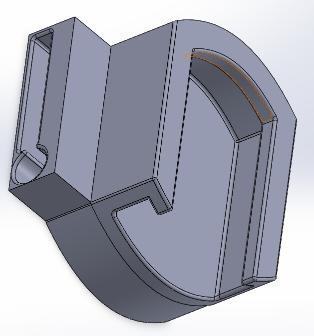
A caddy for implants
I just need to sit down at a PC and CAD design up an implant holder ( I have the design in my head already, so it won’t take long )
The implant holder, if you can imagine, will be an extension of the end caps that slide off withs holes for the xSeries Sizes and a slot for the flexies.
READER END
I have an idea, and it will be pretty simple and should be universal for any reader I want to put in it and allow me to align the reader antenna with the implant…we will see
THE END
for now…