I have already dissolved my card, unfortunately the chip detached from the antenna while dissolving and now i have no idea where to solder the new antenna.
While i wait for the bank to issue me new card, im wondering if any of you smart people can take an educated guess to where the antenna may go.
Try left and right contacts if the chip is in landscape orientation.
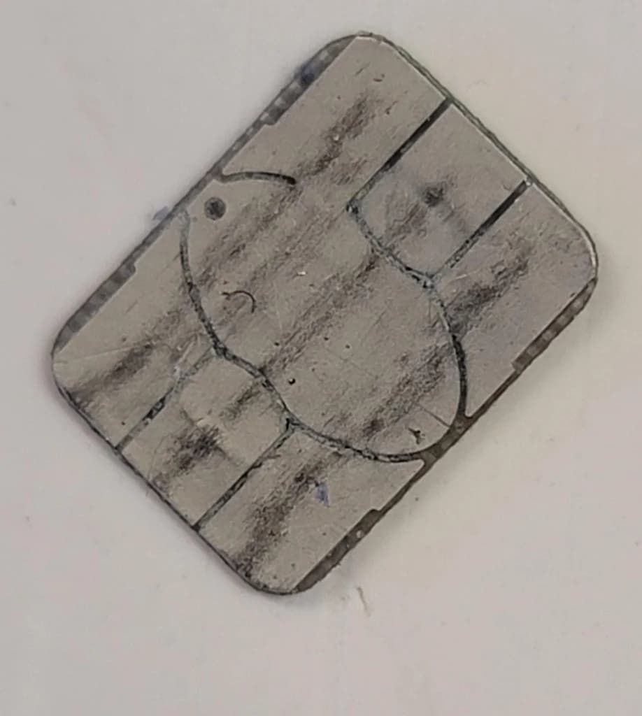
Edit: The squiggly pattern is actually interrupted by the chip epoxy cutout. You can see three orphaned segments. I think this guarantees some area where the wire finds itself above the chip in these spots. I wonder if maybe that squiggly serves as a means to distribute area like a capacitor if it isn’t resting directly on a conductive backside area.
I took a 13.56 MHz access card and was able to grind it down and found that the wires make direct contact with the chip ends. The chip ends here have a larger landing area for the wires and possibly related, no squiggles.
I believe @Satur9 is who you wanna talk to about this
As far as I understand, those chips are not directly wired the the card coil, the squiggle you’re seeing is the coil that sits under the chip and couples to the large card coil
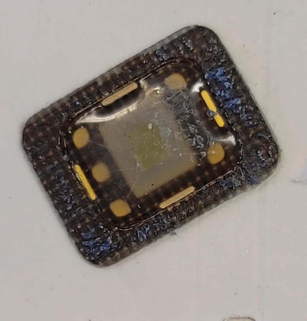
Hey yeah I’m the antenna guy. So this is not in fact a CoM module where the chip and the card antenna are coupled wirelessly. This antenna was in fact connected (spot welded) to contacts on the back of the contact interface PCB. Those contacts were also connected to the bare die of the chip with gold wire bonds. They’re very fragile though, which is why they’re in a dollop of resin. It’s possible one of those 4 wide perimeter contacts were the connection points for the antenna. If so then you would be able to connect a new antenna. You’ll have to check under a microscope or at least get better pictures with your phone to see the wire bonds through the light warping effect of the resin.
If you can figure out where to viably connect an antenna, I can help with the calculations. It would really help to have the Taginfo scan to identify the chip, or a more detailed picture of the previous antenna configuration so I could at least guess the inductance
Thank you! I tried to shine a light through the chip and was unable to see which one of the gold parimeter contacts could be a contact for the antenna. What i assume i see is microscopic gold wires going to each of the square points in the chip and one going to the side where there is no square, if that make sense.
I think it may be easier to just either scrap this chip, or try to just solder on one of the pins and hope that it does not matter which
I also have a similar credit card that is expired, i may just dissolve the card carefully covering the chip so the antenna stays connected and test to see if that works.
I should of dissolved the expired one first as a test, got bit too exited i guess!
Hey, it me. Yeah when I did that ring the antennas on all the cards I tried were just press-contacted onto the chip pads. It looks like most of the chip pads are under the resin blob. If there’s two exposed, try pressing the antenna ends back onto those and go find a vending machine to test. I found I could fairly reliably pinch hard and get it contacted enough to read and auth.
Looks like there might be a deformation in the resin blob to expose two contacts in your pictures, but I can’t see terribly well. Taking pictures of those was the bane of my existance too.
EDIT: I just noticed the first chip you posted was not your actual chip. See if you can take pictures of your chip under a microscope, but the “pinch and pray” method worked well for me verifying what pads were right, and then when I actually went to make the ring I soldered and again tested with buying a soda. Many, many sodas were purchased in the testing of that ring.