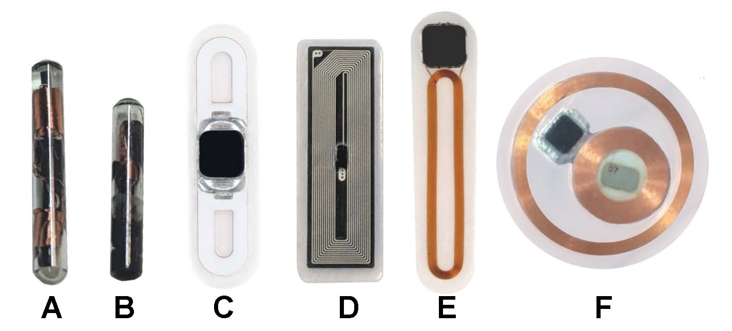
In form type C (flexClass, Apex flex, flexDF2 etc) what are the extra layers that cover the copper antenna? Are they there for aesthetics?
It looks like the chip sits on a platform. Is this form factor thicker than other flexes?
Is there still one antenna loop or two? (one either side of the chip)
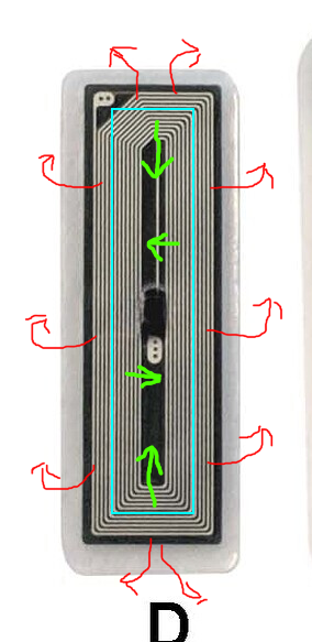
it’s just solder mask overtop the copper. it’s protective i guess… though not really necessary I suppose. the flexNT (D) has a silver ink printed antenna so it looks nifty
Yes it looks great. Being printed silver ink isn’t it a little fragile though? (like the stickers)
Sorry, don’t seem to be able to stop my antenna question splurge!
Not necessarily… typically there needs to be a slight change to the inductor to keep things in tune… but depending on the alignment it may actually improve performance… though in almost every case it’s imperceptible outside lab conditions.
Not necessarily… it can me made robust. No flexNT has ever failed because of the antenna or chip. The module is very well made.
I see you’re using the “C” (from pic above) form factor a lot. Is it more robust? Easier to get good welds between chip and antenna?
Is is the thickest of the flexes?
C is a standard flex PCB so it makes for fast design and easy manufacturing in low qty. The silver ink print is expensive to iterate designs and manufacturing runs must be in the many thousands for it to make sense.
Copper enamel wire doesn’t work long term. The enamel wears with any flexing and fails.
Yes it does have a loop of copper under the solder mask it’s deposited into the PCB substrate with clear division and spacing between each loop of the coil, unlike enamel coated wire which is basically just thinly coated with enamel stuck together with nothing but that thin enamel coating between. It makes for tighter coils of copper but the enamel is not strong enough for this kind of application where there is constant small movement and flexing.
F. Almost Card read ranges, pretty similar to Fobs
D. Amazing read range for its size, and surprisingly robust, Mines in my forearm and I’ll frequently knock it, drop my back pack and catch it on it and it just keeps on ticking.
E. I have and have had a few of these and the read range is really reliable and the only time it may struggle is with a battery powered reader, Padlocks or similar, but in the same breath, some just work really well, hotel doors, chinese relay boards etc.
C. I have 3, they are still very usable, but in my opinion, not quite as good as E., I know why Amal has move away from the copper E.'s but I have had nothing but great experiences with mine which is all I can comment on.
B. & A. have negligible differences between them, But there has been a couple of tests that show an xEM tests ever so slightly better than a NExT
and likewise an xNT slightly better than the NExT
These are so close in performance, it’s barely worth seperating them.
They work well, when you know your implant and know your reader, getting a succesful read should be easily attained.
I don’t have unrealistic expectations of mine, I know they probably wont work with a Hotel lock or door lock, BUT they still could if you find the right one.
I have never had a problem reading mine with a phone, a proxmark3 or a flipper.
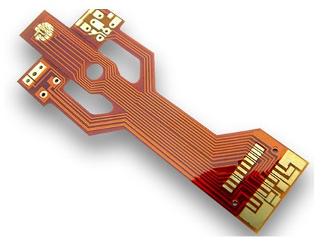
Hey. The standard flex antennas are flexible printed circuit boards. PCBs are made by laminating layers of material together, in this case a polyimide core, a top and bottom copper layer, and a top and bottom coverlay layer. Most of the implant antennas have white or black coverlay, but the standard is a semi transparent orange that really shows off what I’m talking about. The coverlay is important for corrosion resistance (because solder flux can be caustic and normally PCBs are out in the environment), and to reinforce the copper and prevent buckling.
The new ones are not necessarily thicker than the old copper wire antennas. They’re 0.26mm thick with a 0.2-0.4mm thick MOB package chip on top. The old ones used between 0.32-0.5mm copper wire with the mop package coplanar (not adding to the thickness). The copper of each layer on the new FPC is actually only 0.07112mm (2oz/ft^2) thick, so most of the strength is coming from the polyimide core and coverlay, aside from any durability tricks I’ve employed.
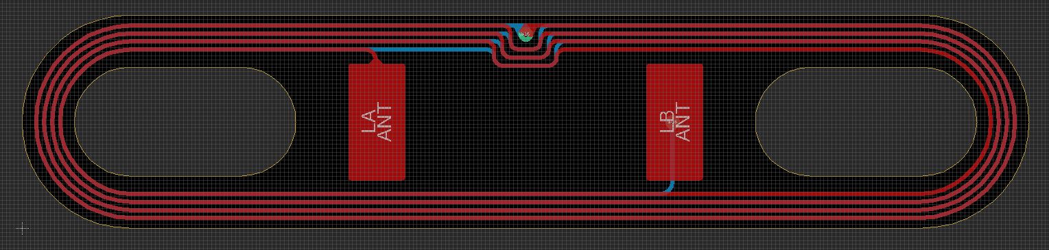
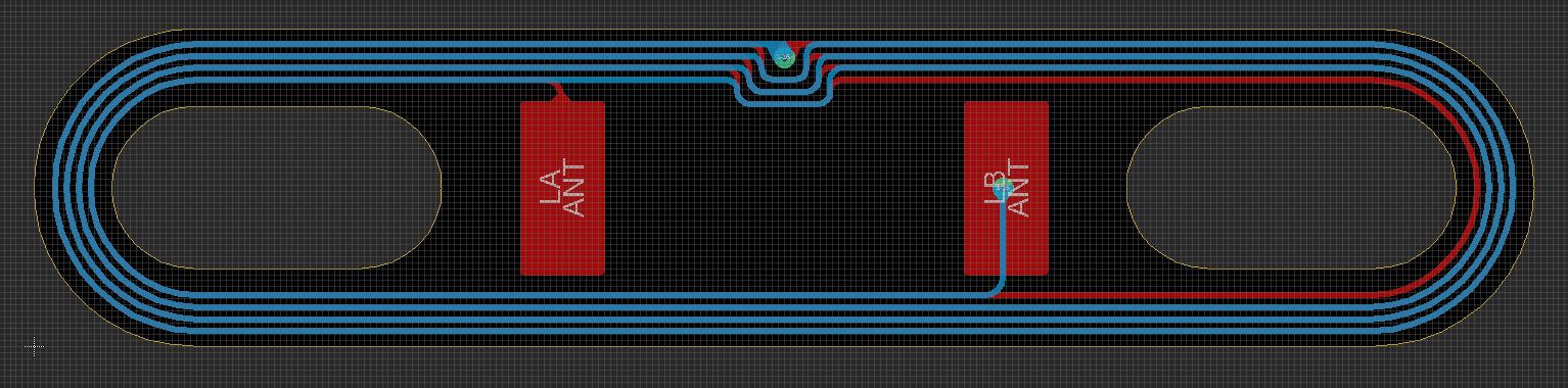
There are 2 for most flex antennas, top and bottom. If necessary for LF we could use a 4 layer FPC, but it hasn’t come up. Here this should help. Red is top and blue is bottom copper layers.
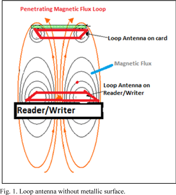
There are a lot of factors that influence how an RFID tag performs. The most important is “coupling factor” which is denoting how much of the magnetic field from the reader is making it through the center of the tag antenna and inducing power for the tag to use and modulate for communication.
If the tag is smaller then there’s less surface area in the center and less of the magnetic field will squeeze through there. The relationship is not linear, so performance increases dramatically with increased tag sizes (until they’re the same size as the reader).
The shape of the coil also affects the coupling. Most readers are large flat rectangles, so they work best with other large flat rectangles. This behavior is why there are orientation “tricks” you need to learn to get the most performance out of an implant. The x-series are the worst case scenario, because they’re not only tiny, but their antenna is a different shape than the reader so it will have an even harder time getting magnetic field through the coil.
Wow, thank you for taking so much time to write such a great answer!
That’s a metric bunch (for PM’s sake) of really interesting information!
Presumably, when the chip has been soldered to the PCB and all its layers, the whole unit is then sealed in biopolymer for implantation.
How does the flexNT work so well without a space in the middle of the antenna?
Is there an advantage to the 0.07112mm thickness, or is that just what is available? It sounds like it would be very delicate with even the slightest flexing.
It does have a pretty significant amount of space in the center relative the the width of the antenna windings. The antenna itself blocks most of the flux from traveling through it, so you can imagine half of the flux hitting the interior side of the antenna turns is squeezed towards the center contributing to the read, and the other half hitting the exterior side is pushed away and wasted.
It could do with a bit more space in the center for better performance, but because of manufacturing constraints with the silver foil printing process and honestly probably a lack of engineering prowess from the designer (could have put some antenna on the bottom too) they needed that large antenna on top to tune the circuit properly without the option of a tuning capacitor. Fortunately the large antenna and small input capacitance on the chip really increases the Q factor which is another thing that impacts performance.
That’s just what’s available. I would like to make it thicker, but 3oz/ft^2 copper is pretty specialized and expensive and would only bump it up to 0.1mm thickness. They antennas are pretty durable despite this. I’ve done a bunch of durability testing. No implant is perfect but I feel these are more than adequate. I’ve also learned a bunch of durability tricks over the years to prevent metal fatigue or tearing on the copper like teardropping and planning via and component placement to reinforce areas and prevent flexing.
Like Amal mentioned the, the wire antennas had issues with rubbing between the windings wearing off the enamel and causing shorts. There’s also an argument to be made that a length of copper with a rectangular cross section is more resistant to full-reversed loading fatigue than a length with a cicrular cross section. Unfortunately I don’t think I’ll be able to do the exact math to prove than hypothesis because the properties of the copper are not only different between the FPC and the wire, but the nominal properties of the annealed copper sheets used in the FPC change during the PCB fabrication process.