Hey all!
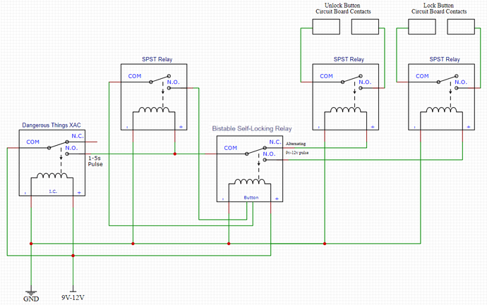
This is a finalisation of a post I made over six years ago in the Support category where I was trying to make a lock/unlock circuit work with a remote that had separate lock and unlock buttons on it.
Originally, I started this project on my 2002 Holden Commodore and between stripping the circuit for parts, selling that car, buying another car and just day-to-day life, it all sort of got forgotten about… until recently.
I ordered a NExT implant in 2021 and it took three years before I found someone willing to install it for me. Once that needle went into my skin, my spark was reinvigorated and I wanted to get back into making this project work and getting some use out of my new NExT and my xEM that I had implanted some six-to-seven years ago. I got stuck into it and here are the results!
Parts Used:
- Dangerous Things xEM Access Controller v2
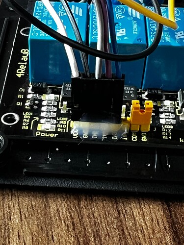
- 4-Channel, 12V Relay Module
- 1-Channel Bistable Latching Relay
- DC Voltage Regulator Module
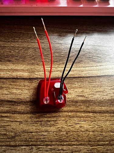
- Key Fob
- 3AG Glass Fuse Holder
- Project (Jiffy) Box
- Various different lengths of wire, Solder and Heatshrink
- Rubber Grommets
Tools Used:
- Cordless Drill
- Screwdriver
- Soldering Iron
- Multimeter
- Side Cutters
- Proxmark3 Easy (but my blue cloner worked fine too…)
The goal was to make the circuit and antenna as invisible as possible, while also making the whole system relatively easy to remove and reinstall if the car is sold. I also added some ‘quality-of-life’ upgrades to the circuit:
-
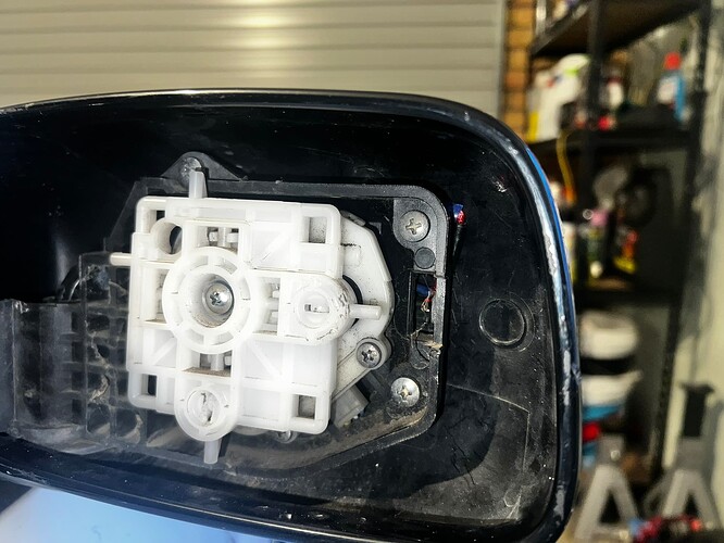
The antenna has been extended and rewired with some new JST connectors so it can be easily replaced if the mirror housing ever gets ‘taken out’.
-
A voltage regulator was added between the car 12V system and the circuit to protect from overvoltage while the car is running.
-
A glass fuse holder was installed to the outside of the box for easy access to a 500mA fuse without having to open the whole thing up in case it blows.
-
All circuit boards now run to the same +12V and GND wire rather than to a distribution box/bus screwed into the door. Now the whole thing runs off just one wire coming out the box, with the second wire being for the antenna itself.
When I removed the old circuit layout, I destroyed the key fob for security reasons. It was no good being placed back in the key shell since the buttons had been ripped off and replaced with wires. I ended up buying two replacements from AliExpress; one for my spare key and one for this project. Thankfully, I know a guy who was able to program them to the car for the low, low cost of a case of beer!
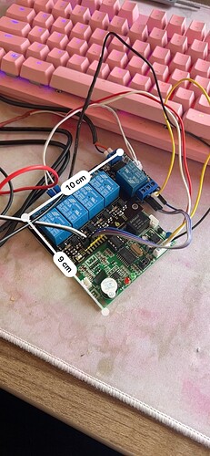
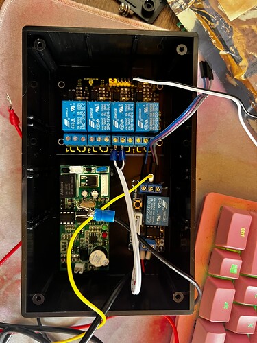
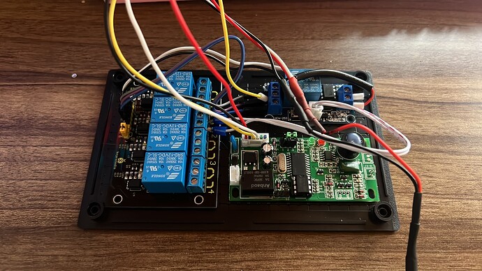
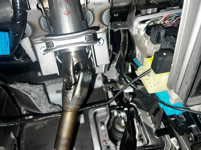
Some Project Photos (will update with more photos soon!)
And here is a video of the whole circuit working as designed!
Thanks again to everyone who has gotten involved in this project, to everyone who has attempted this in the past for all your inspiration and to everyone who has paved the way for making things like this possible to people like me.
Next step from here - RFID Push-to-Start (I see you, @Pilgrimsmaster ![]() )
)
