Xem access controller wiring

Hi,
Quick question, have been experimenting with the access controller and this is what i came up with.


Is this save to use with my door?
It looks a lot different in Amal’s video, but it works.
I don’t want to create a fire hazard :slightly_smiling_face:

I assume the door latch is a solenoid? Do you know the current and voltage requirements? Those jumpers and breadboard can only handle something like 1.5 amps at best, depending on the solenoid it’s pretty easy to go over that. I’d definitely recommend wiring everything directly before installing it.

I also don’t know how much current the access controller is able to handle switching, you should double check that.

I’ll be more use tomorrow when I can actually look at the spec sheet, but those are the two things jumping out at me immediately.

3 Likes

If you’re going to use this on an exterior door, you should check this thread out too before you decide:

3 Likes

This is the solenoid i’ve bought : https://a.aliexpress.com/_EvWijOD

Definitely going to use thicker wires for it.

The door i’m going to use it for doesn’t need to be that secure. There are easier ways to get into this building. The door is mostly for looking secured.

1 Like

So the access controller is using a relay, so it should be fine for your use.

The solenoid is rated for DC12V3A, so make sure your power-supply is rated for at least that much current.

Also be aware that it looks like the solenoid shouldn’t be powered for more than 5 seconds at a time.

I’m confused by your wiring. Do you have the white wire connected to power?

1 Like

No i just used the ground, 12v and yellow wire.
Didn’t use the common (white) wire.

It works for me, just seems wrong.

yeah that seems wrong, I have no idea how that solenoid is getting power.
I think it should be something like this:

Keep in mind I’m an idiot and not well versed in electronics. Follow my advice at your own peril :grin:

Note that if you wire it like this, the green wire will be connected to +12v while the solenoid is off, so make sure to not let that short anything.

Edit:
Just to elaborate, if you compare this wiring to the one on the product page, you’ll see I’m doing high side switching, while they’re showing low side switching. Both will work for this application.

1 Like

My lock was a magnetic one. So not sure if this helps but here’s the thread I had when doing my door lock.

I used this video and come up with these instructions id written out.

I can look at it in person soon and confirm.

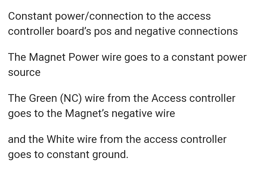
Here’s a pic of what I wrote out.
Hope it helps.

Bear of luck.

2 Likes

In this case the solenoid is normally locked while unpowered (the opposite of a magnetic door), so instead of the green wire, Viktor will need to use the yellow like in my diagram.

This is also an example of low side switching, which is why here ground is connected to white and the negative wire of the magnet is wired to green, instead of +12v connected to white and using the positive magnet wire to green.

3 Likes

Thanks guys!

Still works great.
Time to install it in the real world!

3 Likes

Works great! Just left the white wire loose. This gave a short to the board and resulting in the lock only being open for 1sec.

Thanks again for all the help and ideas!

1 Like