Questions on Initial Setup on Access Controller V2 (Newbie)

Hello,
I’ve just received the Access Controller V2.
And I have multiple questions…

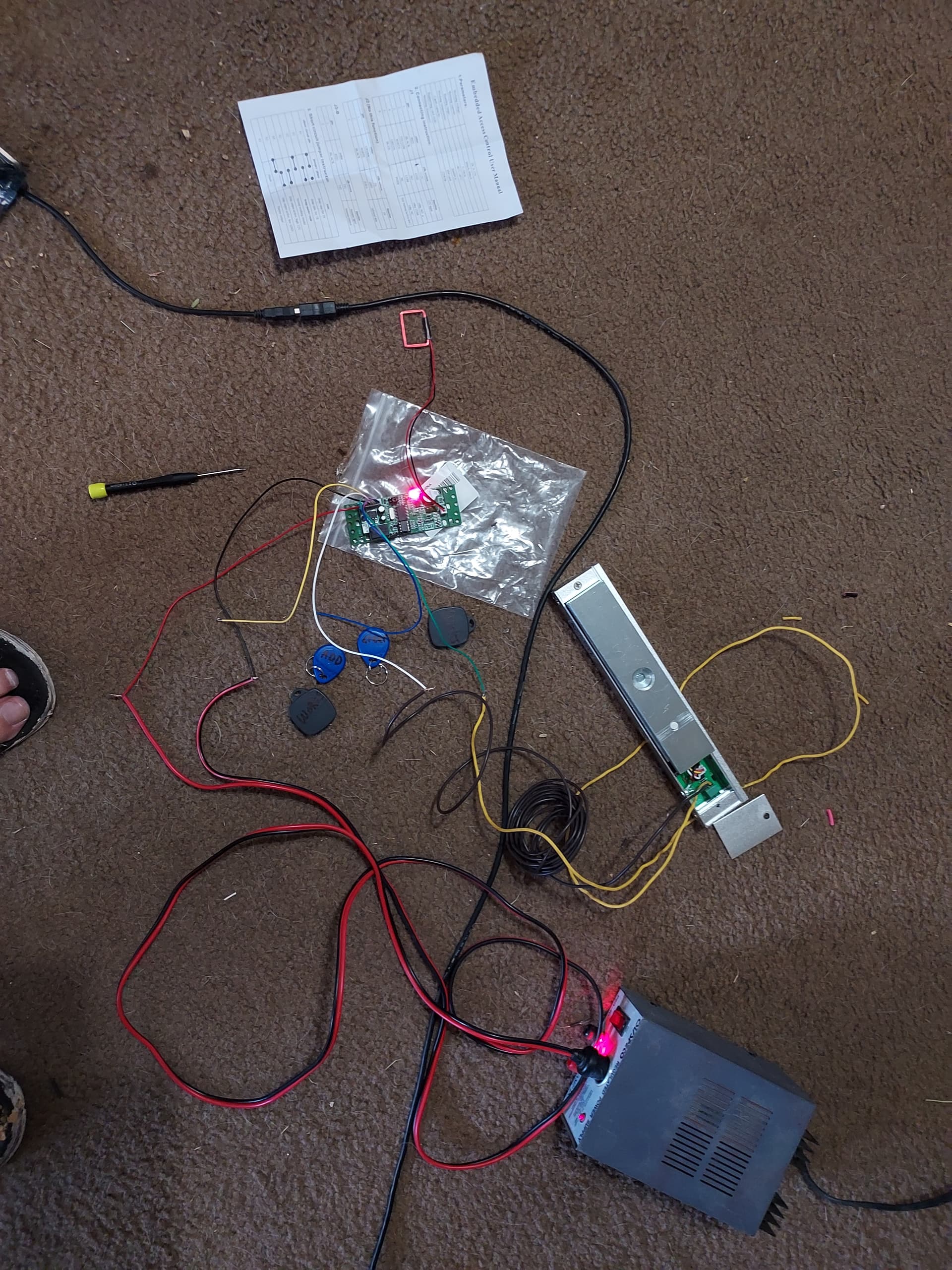
I’m trying to open a magnetic lock, which just has 2 wires, + and -

I’ve gotten the Access Controller set up.
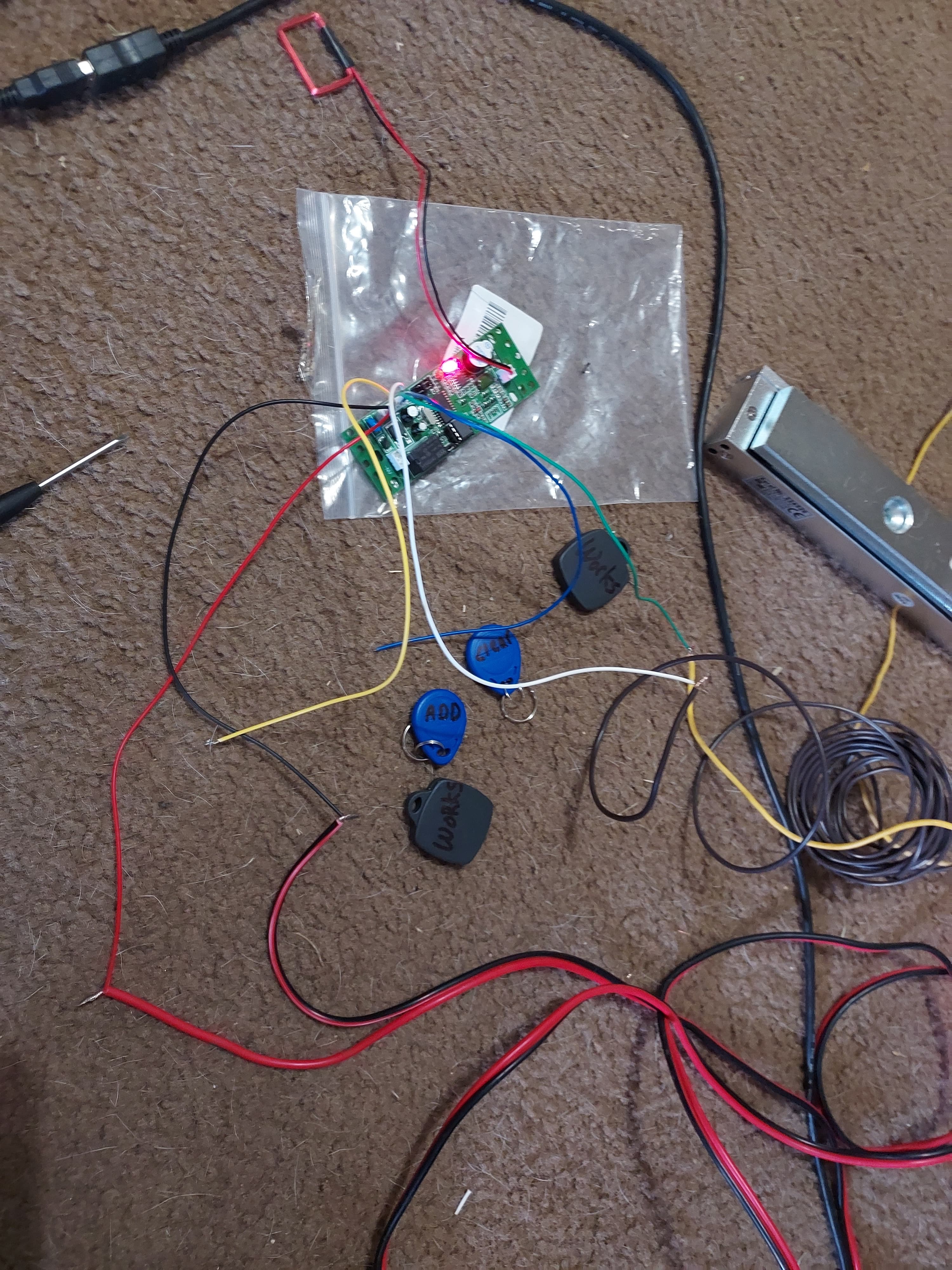
I’ve got the add and clear keys set up.
I added 2 keys that seem to work.

I hooked up the electric magnet to the White (Common) on the V2 to the ground on the magnet
and the Green (Normally closed) on the V2 to the positive on the magnet.
And nothing.
I’m assuming that isn’t right…

I don’t have the control board like in the youtube video, so I think I’ve wired it wrong.
Or need to supply external power to the magnet in some way.

Do I need a separate power supply like in the video? To give power to the magnetic lock?
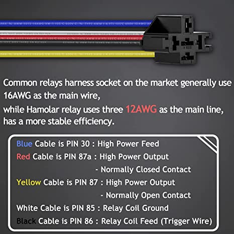
Or a relay between that power source and the controller?
Sorry for my lack of knowledge, I’m trying.

Also, more questions.
I’ve already purchased a few wrist bands, and also a ring (from amazon) that are programmable.
So I’m assuming I wont be able to add them unless I have a proxmark 3 or similar to program them first? They have T5577. Maybe I should just buy some pre-programmed ones for now?

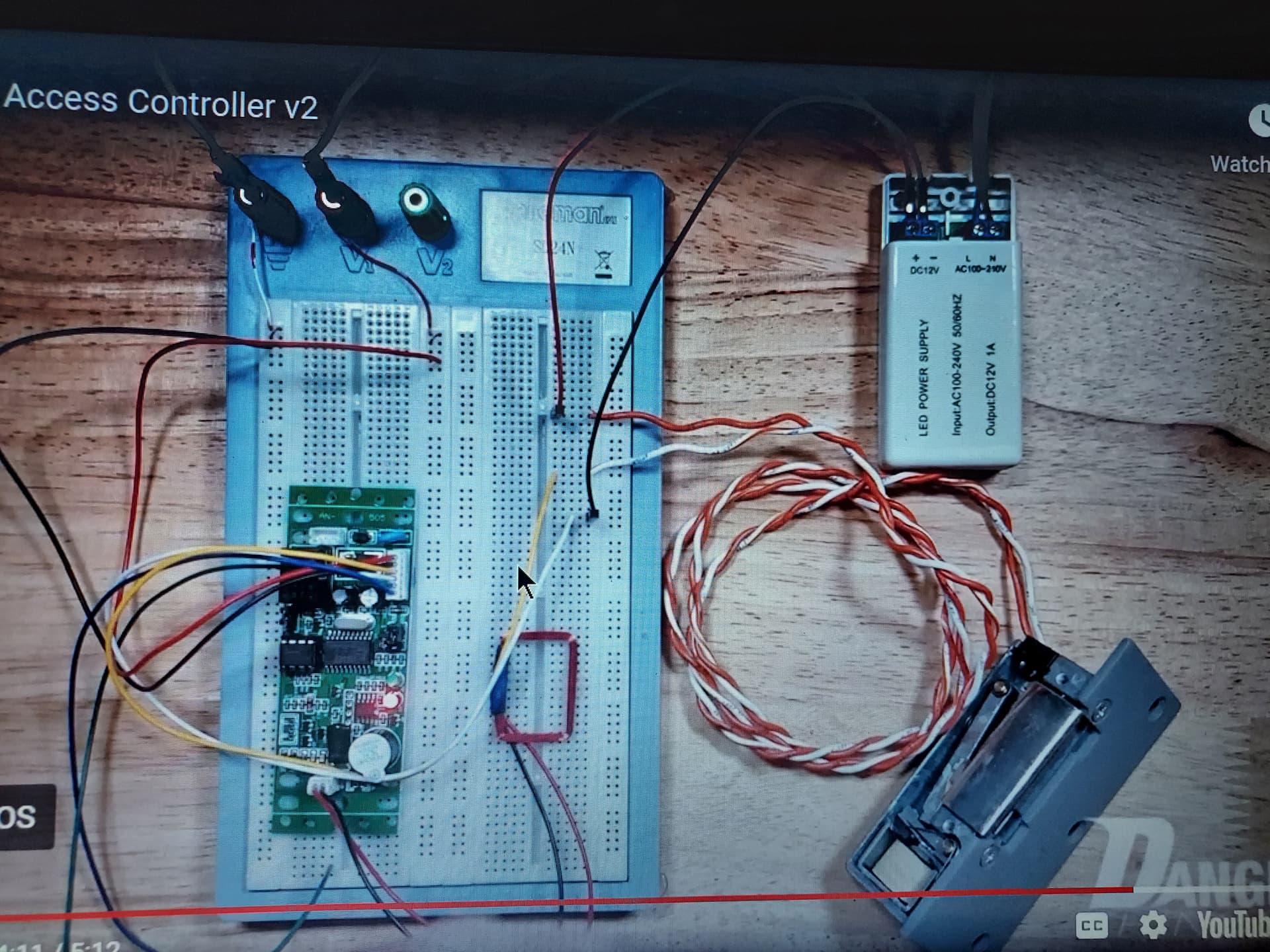
this is the video I’m referencing

This is the wrist bands I’d already gotten, not knowing anything.

This is the ring I got, also without knowing what to get.

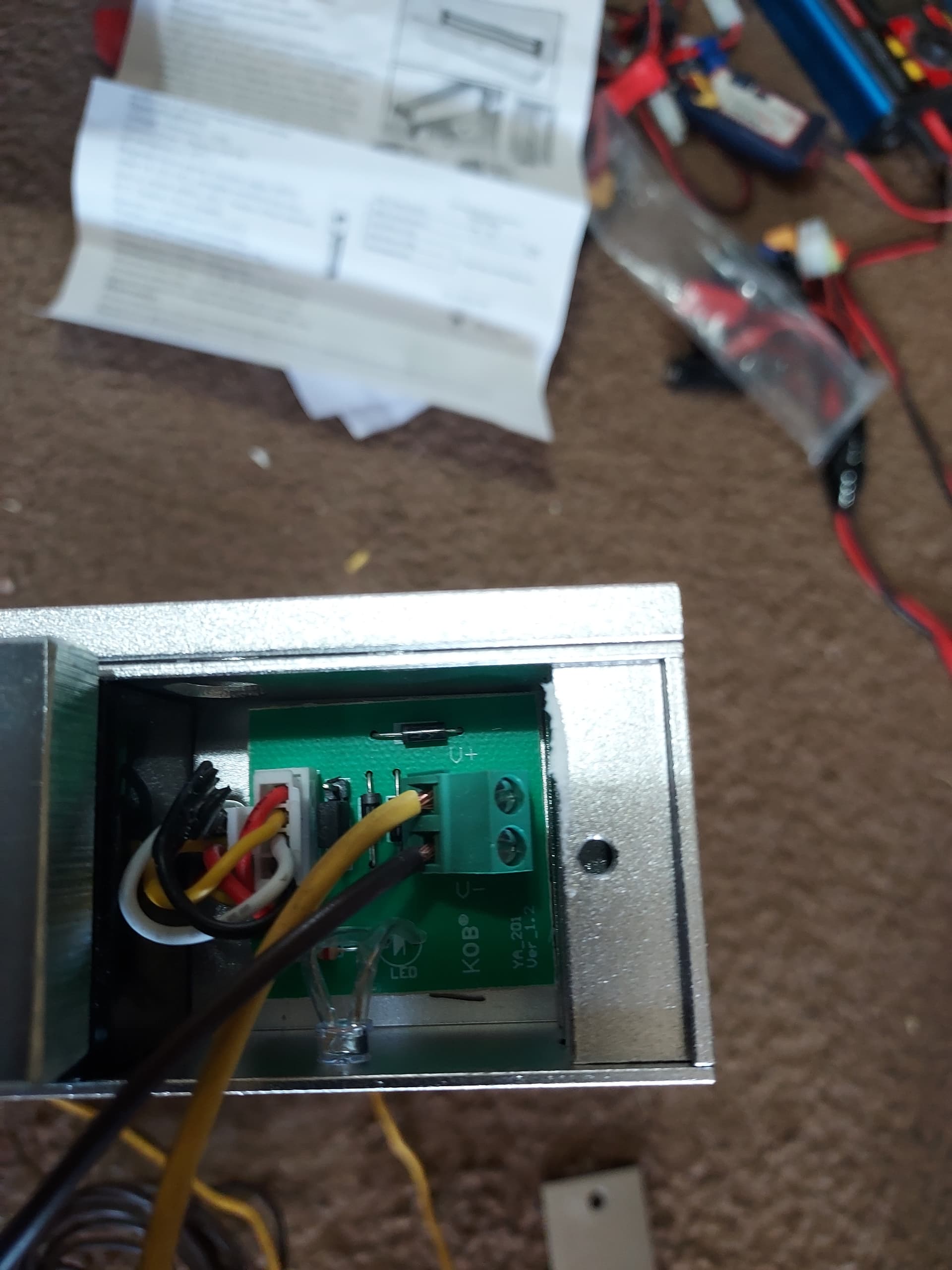
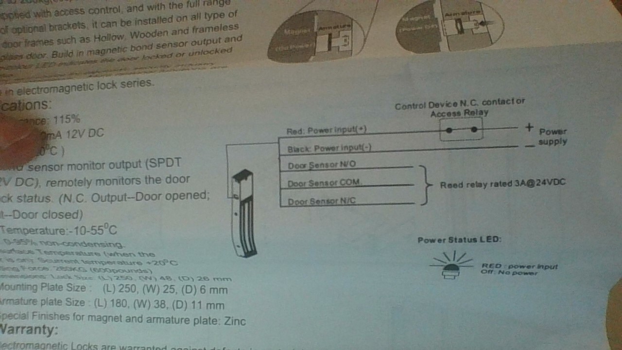
And this is the magnet I’m trying to power.

It says it takes 400ma at 12v

My idea, in getting the rewritable ones, was to be able to change frequencies if anyone ever got access to it.
Not knowing how complicated the Proxmark 3 is.

Hope I worded that to make sense.
What I need the most help with it powering the lock to have it work.
I plan to have two locks in total. And also 3 exit switches. If that information is useful.
It works if just plugged into power, but not the way I’m hooking it up the the controller.

Please forgive me if I’ve used the wrong jargon, I’m totally new to this, and struggling with the learning curve. I’m also going to edit to upload the wiring diagram for my Electric magnet.

Thanks!
Dan

Yes the xACv2 is only a relay for devices, it doesn’t provide any power to them

In my safe builds I had to figure out a power source for the latch mechanism and then place the xACv2 in between that circuit

Post some pictures and or videos…
I’m not an expert but I’ve messed around with the xACv2 enough to probably help

Thanks for the reply!

I’m not sure how to get it between the power source and the latch? (Magnet).
Do I need another relay then? so it can interrupt the power to the magnet?
I’ve been looking online and can’t find anything.

I’ll post pics asap.

I am guessing without seeing your set up but I would have thought 12v power with the board interrupting the positive wire between the power supply and the magnet??

So green wire from board to power source and white common to the positive of the magnet. Then the remaining (neg) wire from the magnet to the negative of the power source.


If those pics aren’t helpful please let me know what to take pics of.

Thanks!

I only see 12v power going to the xACv2

You also need power for the magnet

All the xac does is close the circuit between the white and yellow… it doesn’t provide power

It’s kinda hard to see, but in this you can see the 8xAA I’m using to power the xac, and then the 4x aa pack I’m using to power leds

The xac is only acting like a switch to the led and 4x aa circuit

Hopefully that makes sense

I’m terrible at drawing circuits, maybe @enginerd could draw a basic one and maybe we can get it on the xac page)

Hi Eriequiet,

You are 100% correct. And I know now that I have it wrong. And that I need separate power to the magnet.

I don’t have the arduino (sp?) board, and don’t want to have to use one, as I’m putting it in a vehicle and space is limited.

So I guess I need a relay?
One that takes 12v power in, and then gives it to the magnet for power?
But is also able to take input from the NC and COM from the access controller?
So that it can interrupt that power when I scan my card so the door opens?
(the magnetic lock needs power to stay locked, so it should use the NC hopefully).

I’ve been searching and searching the web to try to find what relay I need and how to use it.

My head hurts.

I appreciate your help!!

Does this work?

Looks like I could connect a separate 12v input for the magnetic lock to the blue wire.

The red wire to the magnetic lock’s 12v + connection

The white wire to the Com from the access controller and maybe to the neg side of the magnetic lock??
and the
black wire to the Green (NC) wire from the access controller

Maybe???

SPDT relay rfid

Thanks TSMC55,
That’s with an ardiuno board?
I won’t be using one in my setup, so am trying to figure out how to do that with a relay or another way.
But you’re correct, I need to have the green wire interrupt the power to the magnet…

I feel like I’m really close to getting this.

No. I think you can hook it up as follows. I am assuming a single 12v dc power supply which doesn’t exceed the capacity of the controller’s relay.

Positive from power supply to the boards positive power in.
Negative from the power supply to the board negative power and also to the magnet negative.
Green wire to the boards positive power input (so you are connecting two wires here)
White common to the magnet positive.

That should work, but again check the capacity of the boards relay. I don’t have one but I would be surprised if it can’t handle 12v across the relay circuit.

Thanks a ton TSMC55,

I’m not following the use of board, so I just want to be 100% certain I’m understanding.

I’ll use power supply as the 120v to 12v DC source I’m using. (it’s only 3A output I believe)
I’ll use Board as the Access Controller V2 circuit board?
I’ll use the magnet as the magnet… lol which just has positive and negative.
And then we’re also using that relay right?

So do I understand this correctly?

1. Positive from the power supply to the:
---- Access Controller power in (Red Wire)
---- Green Wire from the Relay

Negative from the power supply to the:
— Access Controller negative wire (Black Wire)
— Magnet Negative connector

White common wire (from the relay??, there’s a white wire on the Access Controller as well?) to the:
— Magnet’s postive.

2. Or do you mean hook it up without the relay?

So that would mean.
Positive wire from the power supply to:
— The Access Controller’s positive power in (Red Wire)
— Green wire from the access controller hooks to the red power supply and board red’s.
— The Red and Green wires from the Access Controller are hooked together and hook to the Positive from the Power Supply.

Negative from the power supply goes to:
— the Access Controller’s negative (Black) and
— to the Magnet Negative.

White common from the Access Controller to the:
— Magnet Positive.

Sorry if that is dumb. There’s white and green and pos and neg wires on both the relay and access control so I got a bit confused there.

I 100% appreciate your help. I just want to make sure I do it right and don’t burn anything up unnecessarily.

Here is the link for the controller. I don’t see anywhere what the voltage for the relay on it is?
But I just read through the description again and am confused about this part.

I think what I’m looking for is in here if I can interpret it…

Relay wiring and operation
The relay wires are white, yellow, and green. The white wire is the common pin on the relay, yellow is NO (normally open), and green is NC (normally closed). The common wire (white) is the relay pin that will be connected to either the NC (green) pin or NO (yellow) pin, depending on if the relay is active. In the normal state, the common (white) pin is connected to the NC (green) pin. This might be useful for keeping a magnetically locked door secure, since power must be flowing to the magnet to keep the door locked.

Option 2 is what I mean. Sorry when I said board I meant the controller.

Not sure if there is a typo in your post. Are you using 120 volts or twelve volts? If you are stepping down from 120v to 12v make sure the green wire is on the twelve volt side. Don’t try to put 120v across the relay in the controller.

Also just checking your power supply is dropping down to 12v DC? I don’t believe the xEM controller works with AC.

Hi!
Thanks!

There was an error in my post. I had put 120v to 12v AC but it should have said DC (I corrected it).

So I have 12v DC coming in to the access controller.

Option 2? Yay. That means I can try it without waiting for the relays I ordered.
I am looking at the video and the board they have set up. I think i just made sense of the board.

It looks like he has

Constant power/connection to the access controller board’s pos and negative connections

The Magnet Power wire goes to a constant power source

The Green (NC) wire from the Access controller goes to the Magnet’s negative wire

and the White wire from the access controller goes to constant ground.

Does that seem right going by this picture?

I’ll look at your directions again and see how that lines up.

Thanks!
Again, I think I’m very close! haha.

hmm, that’s way off from what you had said.
So now I’m back to being confused.

I might need to order another access controller asap for when I burn this one out, haha.

I appreciate the help!

I just ordered 2 more controllers, so I’m going to go try it, haha.

I’ll post back any results!

Yes. You can have two seperate power sources. However the draw here should be very low so one power source should work.

I used the same power source, since I only have one…

I hooked it up like the picture…

And it works!!!

woo hoo!!!
I’m so excited!

Thanks soooo much for the help!!
:partying_face: :partying_face: :partying_face: