Finally got around to ordering the NFC coil antenna test board. Should be here next week. I’ll post the analysis after they come in.
2 Likes
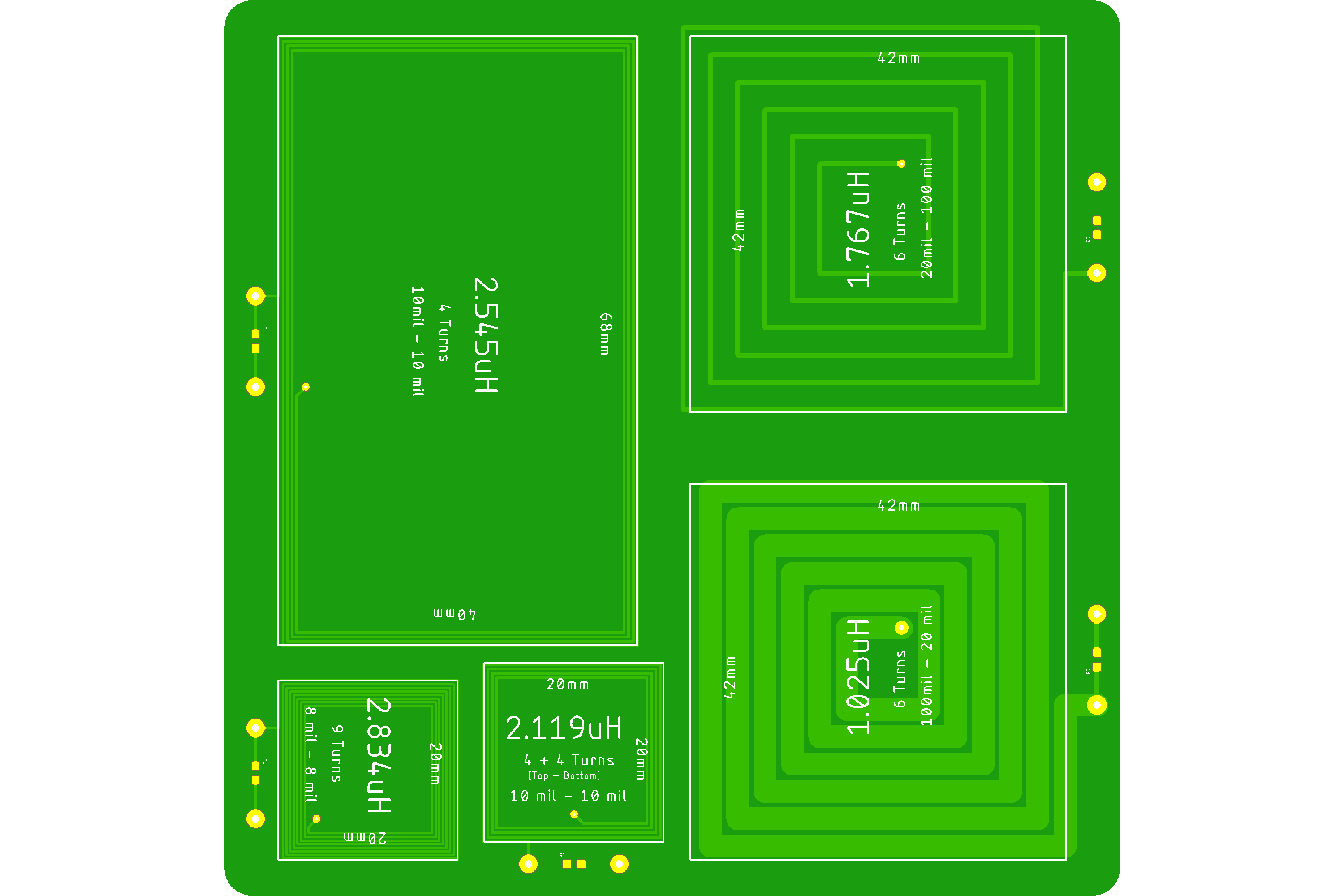
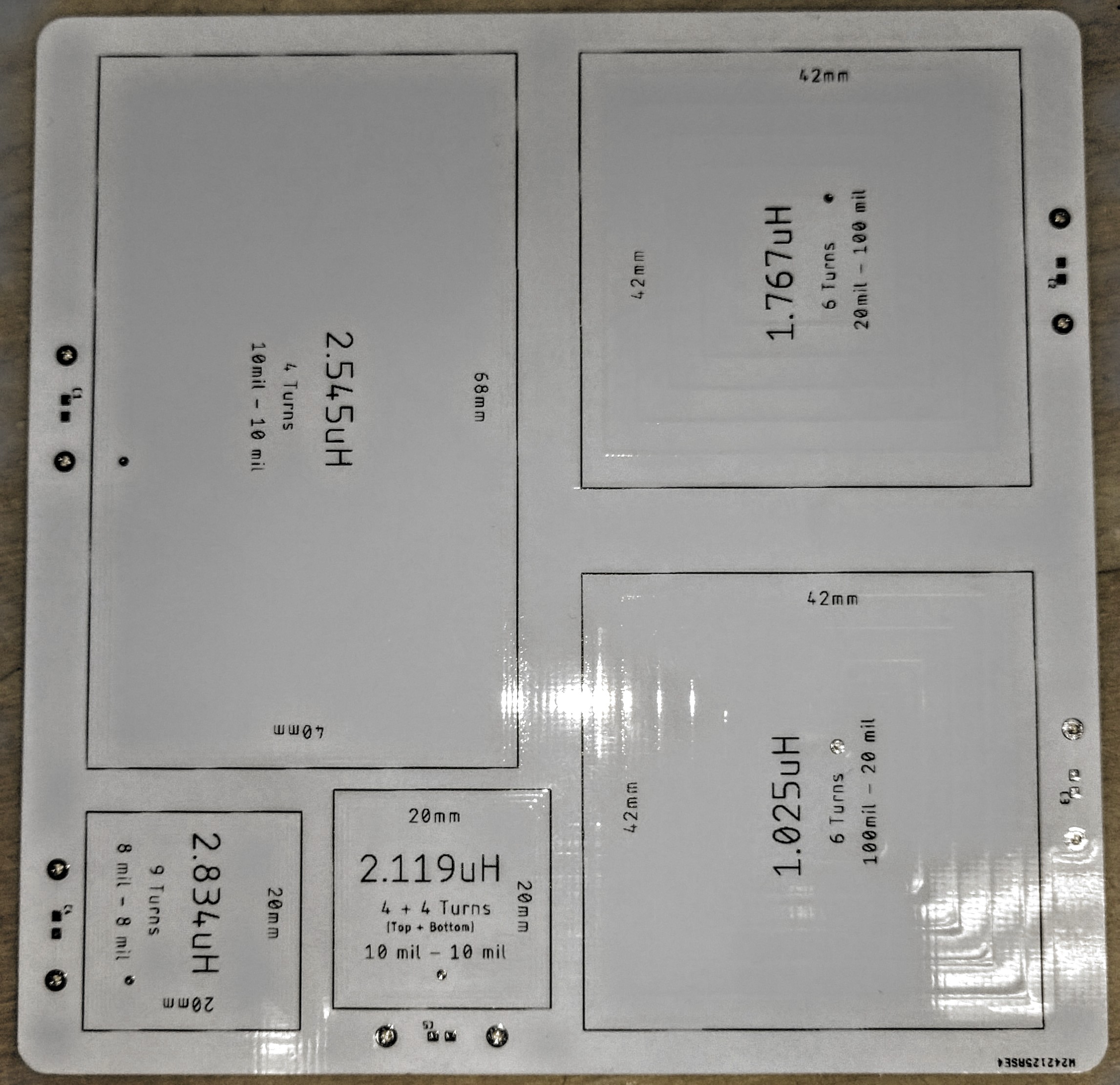
Boards came in. Results varied, but at least it provided some valuable data. The coil parameters are written on the board silkscreen. All of the copper weights were 1oz/ft^2.
Here are the results of my measurements with a quality LCR meter.
2.545μH coil: (L = 2.68μH)(R = 1.4Ω)(Q = 0.013)
2.834μH coil: (L = 2.11μH)(R = 1.2Ω)(Q = 0.012)
2.119μH coil: (L = 2.13μH)(R = 0.9Ω)(Q = 0.016)
1.025μH coil: (L = 0.79μH)(R = 0.05Ω)(Q = 0.06)
1.767μH coil: (L = 1.18μH)(R = 0.4Ω)(Q = 0.017)
I think most interesting was the 2.119μH coil, which was spot on. It was composed of 8 turns, 4 on top and 4 on the bottom, which all traveled clockwise. The board thickness was the standard 1.6mm FR-4.
4 Likes
Love your work @Satur9

3 Likes
Watching this thread with intrigue because I’d like to make a glove that powers my led. Lots to learn!
What board is in the back of the mockup xLED?![]()
Great work being done here by all participants, I’m following Leeborg’s project with great enthusiasm ![]()
![]()
For all the topics related to Leeborg’s project, you can check out this project thread:
There’s a sample circuit over there that you can build. We’re very close to passively lighting an xLED. More input would be appreciated.
1 Like
Oh, I’m already following the thread @Satur9 , and I do have a bunch of the 13.56mHz crystals waiting to be used, just waiting for the oscilloscope to arrive so I can make sure I’m on the right track ![]()