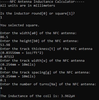
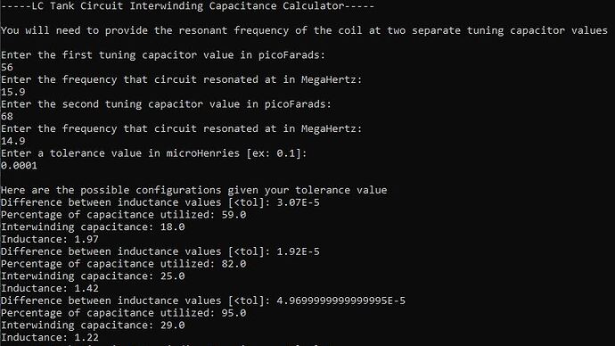
I connected some more dots and made another useful tool, so I thought I would share here.
Here are two zips. One contains an inductance calculator for flat coils that I made a few years ago. The other contains a new interwinding capacitance calculator that I just made. They are both executable java archives. All you need to do is have java and click on the little batch file I put in there to launch them.
Inductance_Calculator.zip (106.3 KB)
Interwinding_Capacitance_Calculator.zip (3.1 KB)
The thing I mapped out more accurately has to do with the inherent capacitance that a coil has, which I’ll call “interwinding capacitance”. This makes mapping out the properties of a coil very difficult because you cannot measure this capacitance directly with a meter, as the coil itself is a short. One easy way to discover this value would be to measure the “self-resonant” frequency of the coil by shorting it to itself with no other components. The trouble is, if you don’t know the inductance of the coil, then you have two unknowns and cannot find either with any certainty.
The way I’ve been getting around that limitation is connecting my coils to two different tuning capacitance values and recording their resonant frequencies. I then try out each combination with a variety of different interwinding capacitance values added until the difference between the resultant inductance values is at a minimum. I then know what the most likely inductance and interwinding capacitance are. For some of my tests though the resultant inductances were very different, and the minimum I was looking for would only come about if I applied a negative interwinding capacitance value.
The key element I was missing has to do with the quality of the coupling in a coil (which I explained above). If your tuning capacitor is rated for 16 Volts, but your resonant circuit has poor coupling and only induces 5 Volts peak-peak in the coil, then the tuning capacitor does not have enough driving force to fully fill its plates with charge, which means the utilized capacitance value is much lower.
This program iterates through each percentage point of potential capacitance utilization, and within each of those it checks interwinding capacitance values from 1-100pF. It then lists any results that are below your tolerance threshold. For a birds eye view I would start with a large tolerance value like 0.1uH and let it run, generating a very long list. You can see where the peaks and troughs are in the resultant data set and rerun the calculator with a smaller tolerance. There will be many possible configurations, but you can use your data from the inductance calculator or measure the coil directly with an LCR meter to get a ballpark inductance value and work from there.
Here’s the math that iterates to find the inductance and interwinding capacitance if anyone is interested.
public static void minimize() {
	double L1;
	double L2;
	double diff;

	for(int i=1;i<=100;i++) {
		for(int j=1;j<=100;j++) {
			L1 = 1 / (4 * (Math.pow(pi, 2)) * Math.pow(res1, 2) * ((cap1 * (i * 0.01))+convPico(j)));
			L2 = 1 / (4 * (Math.pow(pi, 2)) * Math.pow(res2, 2) * ((cap2 * (i * 0.01))+convPico(j)));
			diff = Math.abs(L1 - L2);
			diff = sigDigRounder(convMega(diff),3,1);
			if (diff < tol) {
				utilPerc = i;
				interWindC = j;
				ind = sigDigRounder(convMega(((L1 + L2) / 2)), 3, 1);
				System.out.println("Difference between inductance values [<tol]: " + diff);
				System.out.println("Percentage of capacitance utilized: " + utilPerc);
				System.out.println("Interwinding capacitance: " + interWindC);
				System.out.println("Inductance: " + ind);
			}
		}
	}
}

