I’d call it a coupling extension since a patch is specifically two coils connected by a bridge.
1 Like
He mentioned in the video you would just replace the chip with a capacitor of the same capacitance as the chip.
Ah okay, I must’ve missed that. My bad…
Okay, I managed to overcome laziness and drag my ass to the lab, and I made a booster coil of my own. Here it is, superglued to my hand:
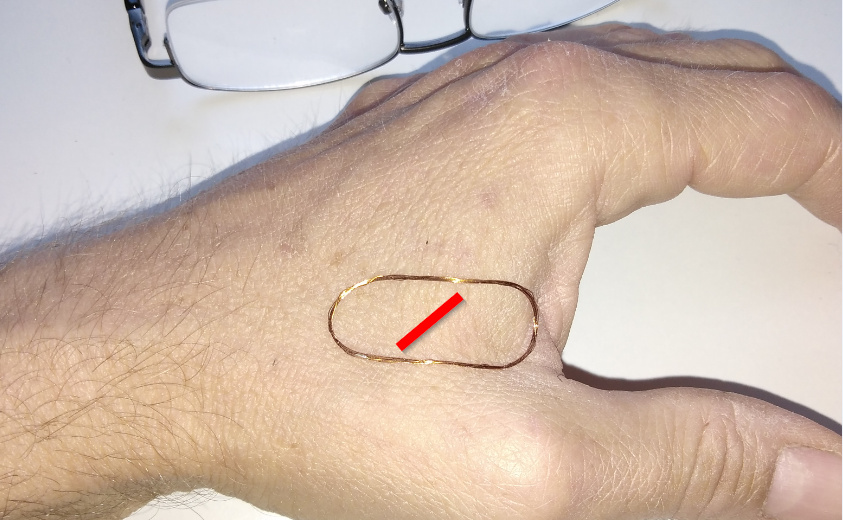
It’s 8 turns and 22 mm in diameter. It had a 60 pF cap, but I removed it because it made things worse for some reason The red line indicates where my M1k implant is.
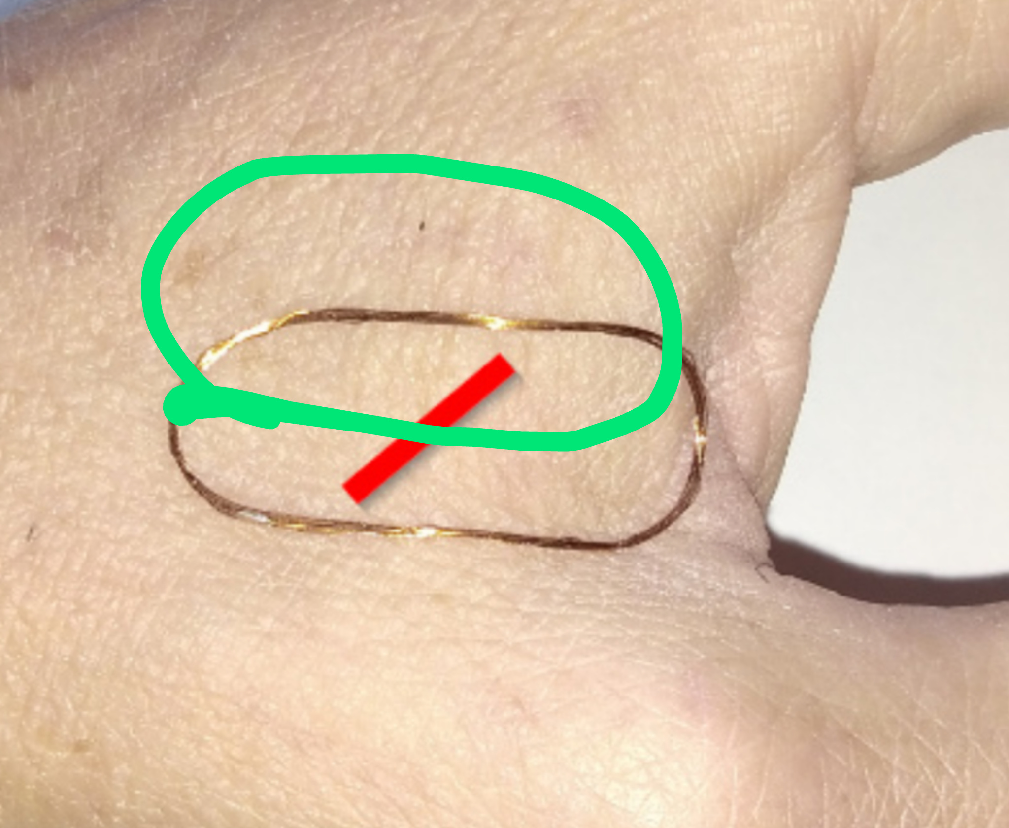
I find it extremely position-sensitive: where it sits now, it roughly doubles the range of the M1k. But if I move it just a few millimeters, it does nothing at all. Worse: in certain positions - particularly with the wire crossing the chip perpendicularly the way Amal seems to get the best results, it plain kills the signal. Nothing will read it. It seems to work best with that elongated shape and the chip in the center about 45 degrees.
Strange. At any rate, my finding is that it’s not an easy placement to get any sort of results…
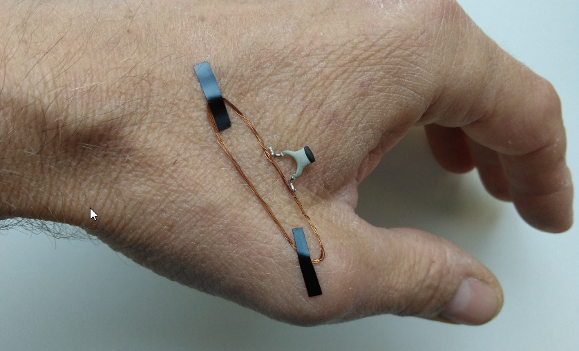
I soldered the cap back on. I think maybe I messed it up earlier because I couldn’t be bothered to drag the magnifier lamp out of the cupboard.
So, with the cap, the best result seems to be with the coil even more elongated, and crossing the chip perpendicularly twice:
This is not terribly practical if I’m honest ![]()
1 Like
Maybe putting it on the reader semi permanently would be helpful without being quite so impractical
The issue is that you are not cutting across the actual coil of the xM1… check the video again… with the cylindrical antennas you need to cut across perpendicular to them… in the center they dead out… so more like this…
Like I said, in that configuration (without the cap), if I place it there, the chip becomes unreadable. Don’t ask me why, it makes no sense.
Also, it’s not an xM1. I don’t think it makes much difference, but just sayin’
Playing with ferrite…
This moon crescent-shaped piece of soft ferrite capping the implant (in red) is what I found to yield the best results. It extends the range a bit (maybe half as far again as the naked implant), but mostly makes it much less finicky to find the sweet spot:
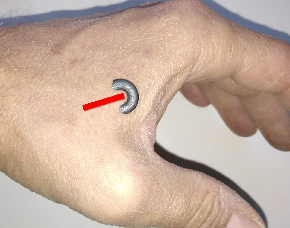
The performance boost is nothing to write home about though.
Mostly what’s to take home with ferrite is, if it’s over the implant, it totally shields it and the implant is unreadable.
2 Likes
Haha well it’s because the shape of the flux lines that the flat coil is “boosting” or rather reshaping is rotated 90 degrees along the x axis from the flux lines that the cylindrical antenna coil windings would achieve the most saturation. By cutting across it perpendicularly, you expose enough of the cylindrical coil’s inductive “surface area” to achieve a minimum necessary voltage… though it’s still not ideal, which is why you see the xLED only kinda sorta half light up.
Because I lack any 3D visualization tools, some resources…
First, flux…
But this describes flux of a permanent magnet not EM fields created by electron flow through a wire, which are rotated by 90 degrees…
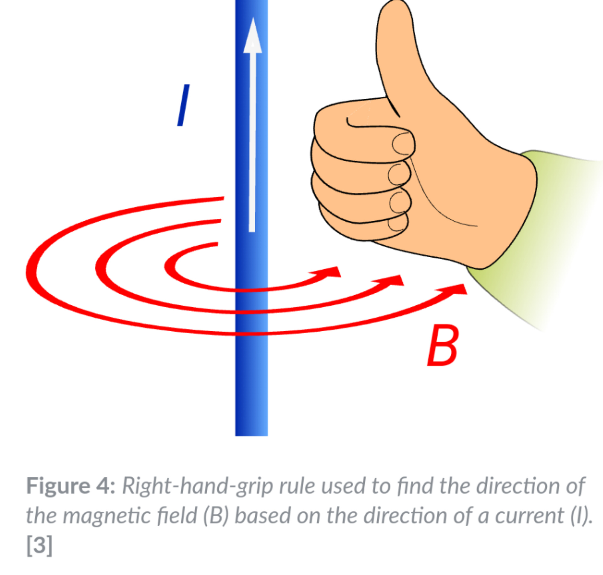
And now you want to induce current into another wire…
But of course, these examples and just about every other example you’ll find talks about straight wire, not a coil of wires, and definitely not a coil of wires wrapped around a ferrite rod… but just consider the mind bending necessary here. The “booster” coil (in my example) is a spiral coil that has a number of turns which are laid out along a flat plane of expanding diameter… so that is flux resulting in current carrying wire where the current is all moving in the same direction…
The cylindrical coil in the implant is a spiral also, but not one that spirals along the x plane with diameter expanding with each turn… it retains the same diameter and spirals along the z plane… and to complicate things it has a ferrite rod core which further manipulates the shape of magnet fields passing though and around it.
In short, it’s complicated.
1 Like
So we’re messing with Ley Lines now huh.


3 Likes
talking in PM but I thought this was so cool I wanted to share…
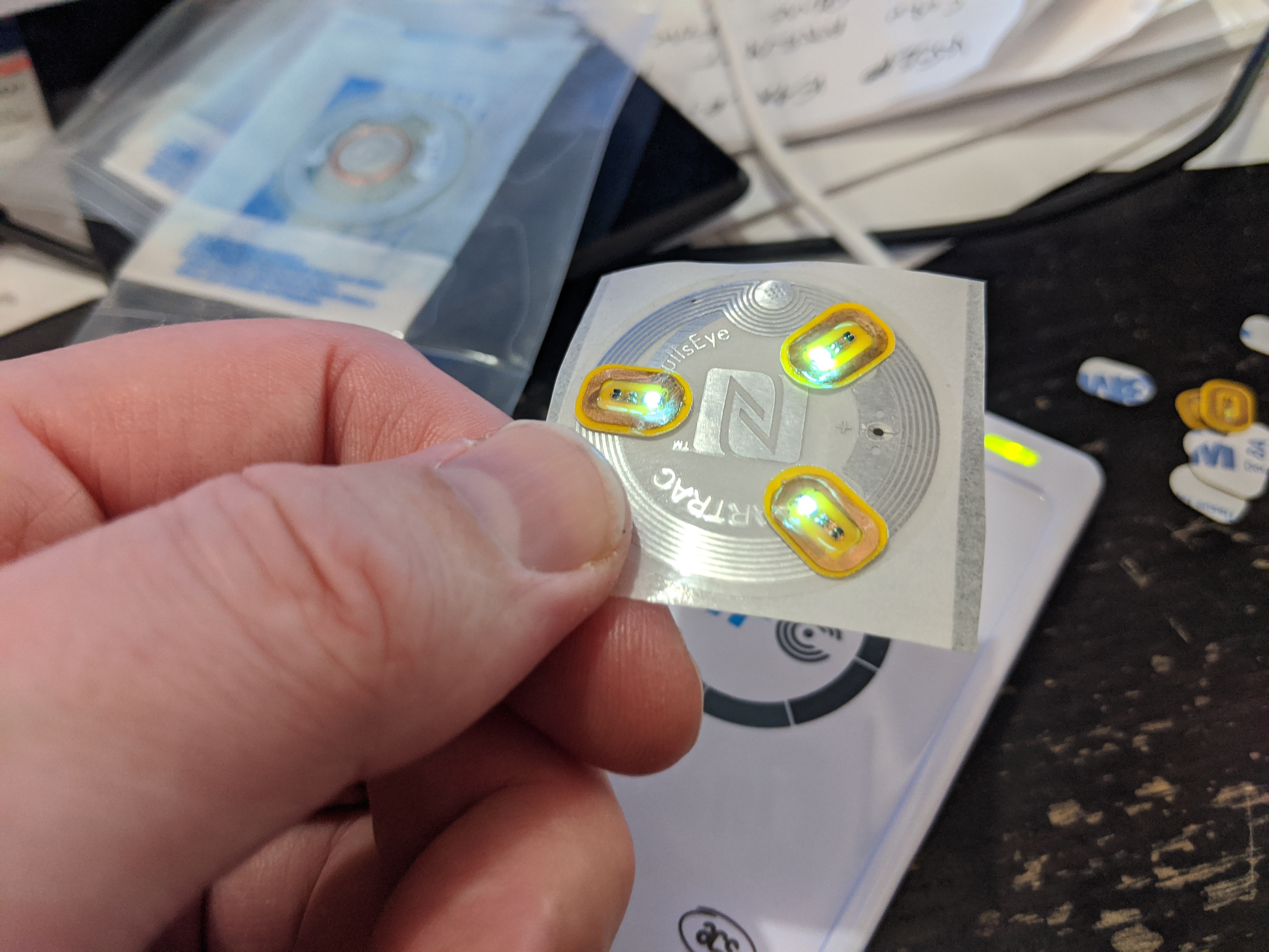
it also works pretty awesome with a phone…
7 Likes
Okay now we talkin. This is getting interesting…
Can you still fit a flexEM in the middle? Does it impact the light?

What’s the range there? looks like ~10cm?
1 Like
no the range is still enhanced by the NTAG216 antenna… but only if I am very careful with placement…
yep…

8 Likes
The big tag is a ntag216?
yeah… basically a flexNExT with blinkies ![]()
1 Like
Any chance this is possible with payment micro card conversions? Or is the big chip antenna powering the LEDs?
I woudn’t do it, but it seems like it could be an extra feature.
1 Like