Uhhh…I’ll be back for an update shortly…
3 Likes
Hehe, thats the noob catch lol.
3 Likes
Is this good?
[=] ---------- LF Antenna ----------
[+] LF antenna: 10.92 V - 125.00 kHz
[+] LF antenna: 11.34 V - 134.83 kHz
[+] LF optimal: 32.78 V - 218.18 kHz
[+] LF antenna is OK
[=] ---------- HF Antenna ----------
[+] HF antenna: 32.54 V - 13.56 MHz
[+] HF antenna is OK

[+] Displaying LF tuning graph. Divisor 88 is 134.83 kHz, 95 is 125.00 kHz.
Edit: Nevermind. I see that the “LF optimal” is what I should be looking at so 218.18kHz isn’t good.
Well at least it’s working now ![]() Yeah it’s obviously high in frequency so you need more turns.
Yeah it’s obviously high in frequency so you need more turns.
Dang it! I ran out of space and I’m still not close to 125kHz
[=] ---------- LF Antenna ----------
[+] LF antenna: 13.35 V - 125.00 kHz
[+] LF antenna: 15.14 V - 134.83 kHz
[+] LF optimal: 40.67 V - 171.43 kHz
[+] LF antenna is OK
I have enough ferrite and wire to try another day.
You can layer it ![]()
1 Like
Glad I let @Nimus go first lol
Absolutely would have forgotten about that
1 Like
Would it still work fine with the extra wire soldiered on? I accidentally cut the wire too short so I’d have to add some more. Sorry for all the noob questions.
Are you using an LCR meter?
If not does that mean I can skip it on my parts list?
Yep, just make sure the joint is tidy, I mean of course would be better not to have solder joints but it will work fine.
Well, it’s not pretty but
Thanks for he help everyone! I’ll try to stop embarrassing myself with these questions…
1 Like
It’s all part of learning! Now you know and can help point out the same potential issue in other people’s troubleshooting ![]() this was actually helpful to me since I’m gonna try making my own antenna in the near future and I’m quite sure I could have made the same mistake so… thank you
this was actually helpful to me since I’m gonna try making my own antenna in the near future and I’m quite sure I could have made the same mistake so… thank you ![]()
Nimus, pm your address, I’m going to 3D print the mount like what compgeek used, I’d be willing to mail you one
1 Like
I appreciate it but there’s no need. I just got my Ender 5 in the other day (upgraded from the MP Select Mini).
Weird thing is is the antenna that I made doesn’t work with my implant. The field detector will flash at 1cm away but it doesn’t detect my implant. It reads the test card just fine so I know the antenna works, and the stock antenna detects my NeXT fine so I know that works. I’m confused lol
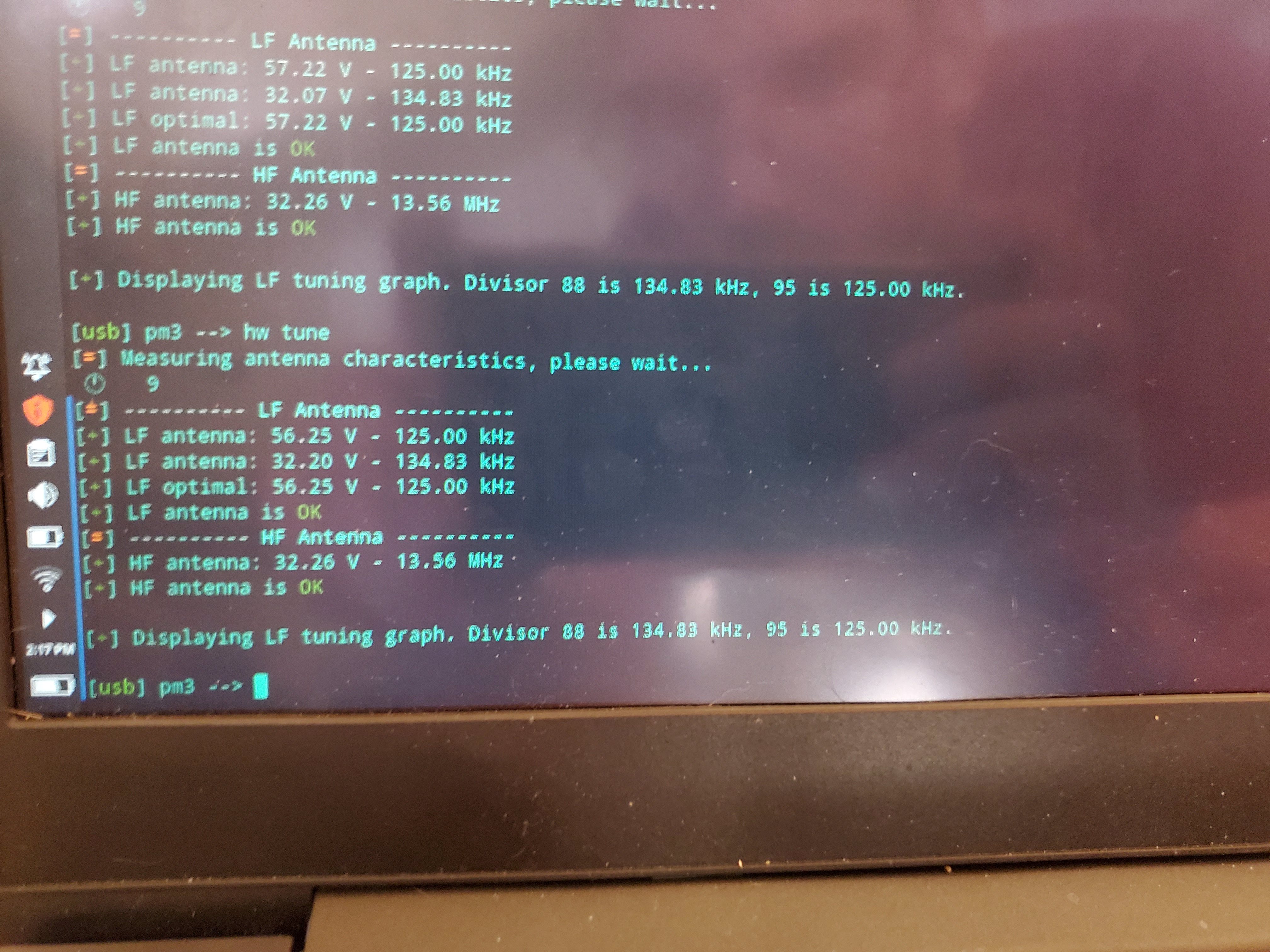
Potentially the voltage is too high? 56.25V is quite high, the designer of the proxLF chose not to go over 26V:
To reduce it, you could try adding a resistor, compgeek added a 47 ohm one to bring 70V down to 30:
1 Like
I have some resistors so I’ll try that out. Would i just bridge the resistor between the two ends of the wire?
From what I understand, it was placed in series - i.e. between one end of the wire and the proxmark 3 easy
1 Like
yo can you throw me the stl? i’d love to print one myself
2 Likes
The lowest I had was a 68 ohm resistor. I added that in series and it dropped the voltage to ~19v. The antenna gets a read sometimes now but it has to be in the exact right spot (it’s harder to use than the stock antenna). I’ll tinker with it some more another day.
Its good to hear that it now works somewhat, definitely would be worth tinkering with some lower resistors and potentially some more tuning to get it even better!
1 Like