DIY LF antenna for Proxmark 3 Easy

Hey everyone!

This post isn’t a tutorial, but theres a lot of things you’ll be able to take away from this if you’re wanting to build you own. Figured if I’m already making one, I may as well share my journey and write it up for those playing along at home!

Thanks to @TomHarkness for getting me on the right track with this - without further ado, let’s get this project started!

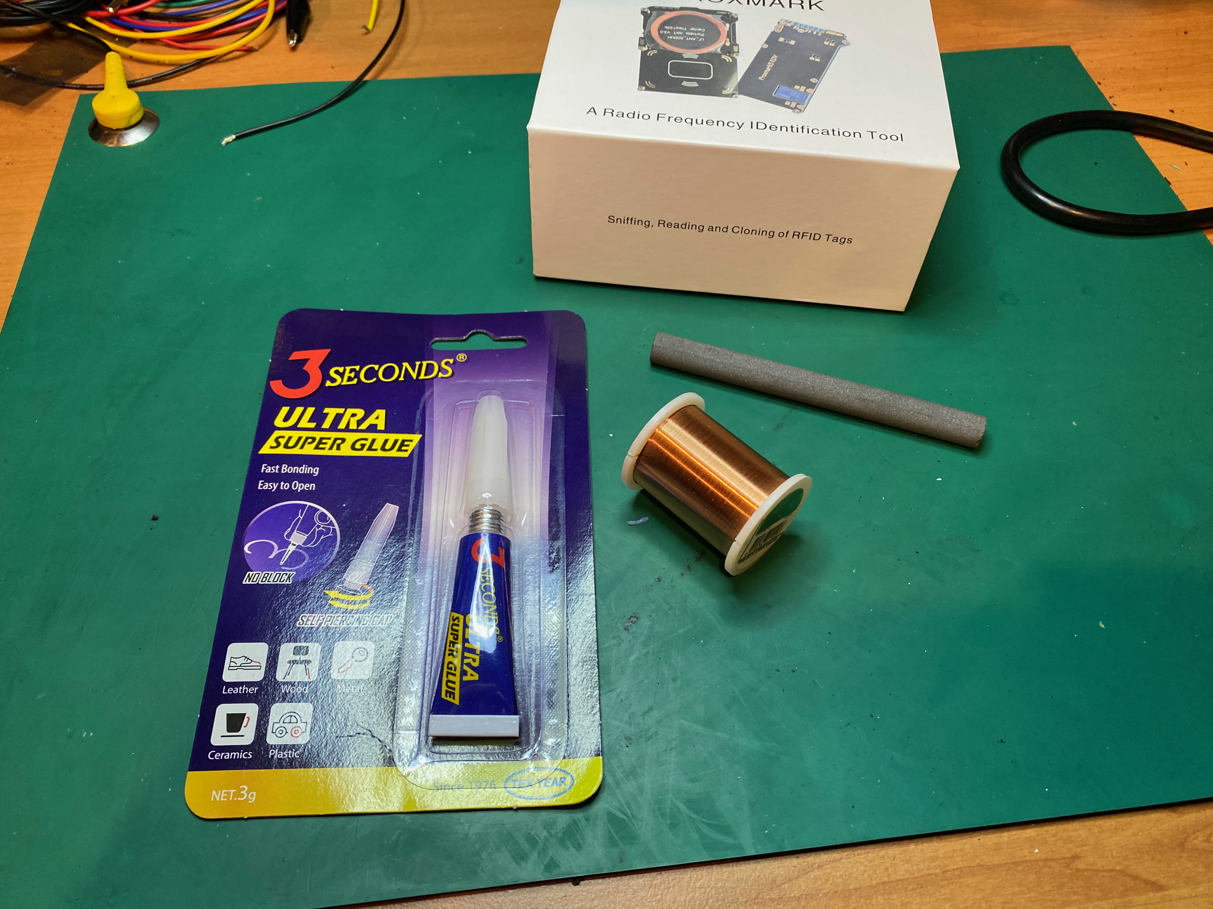
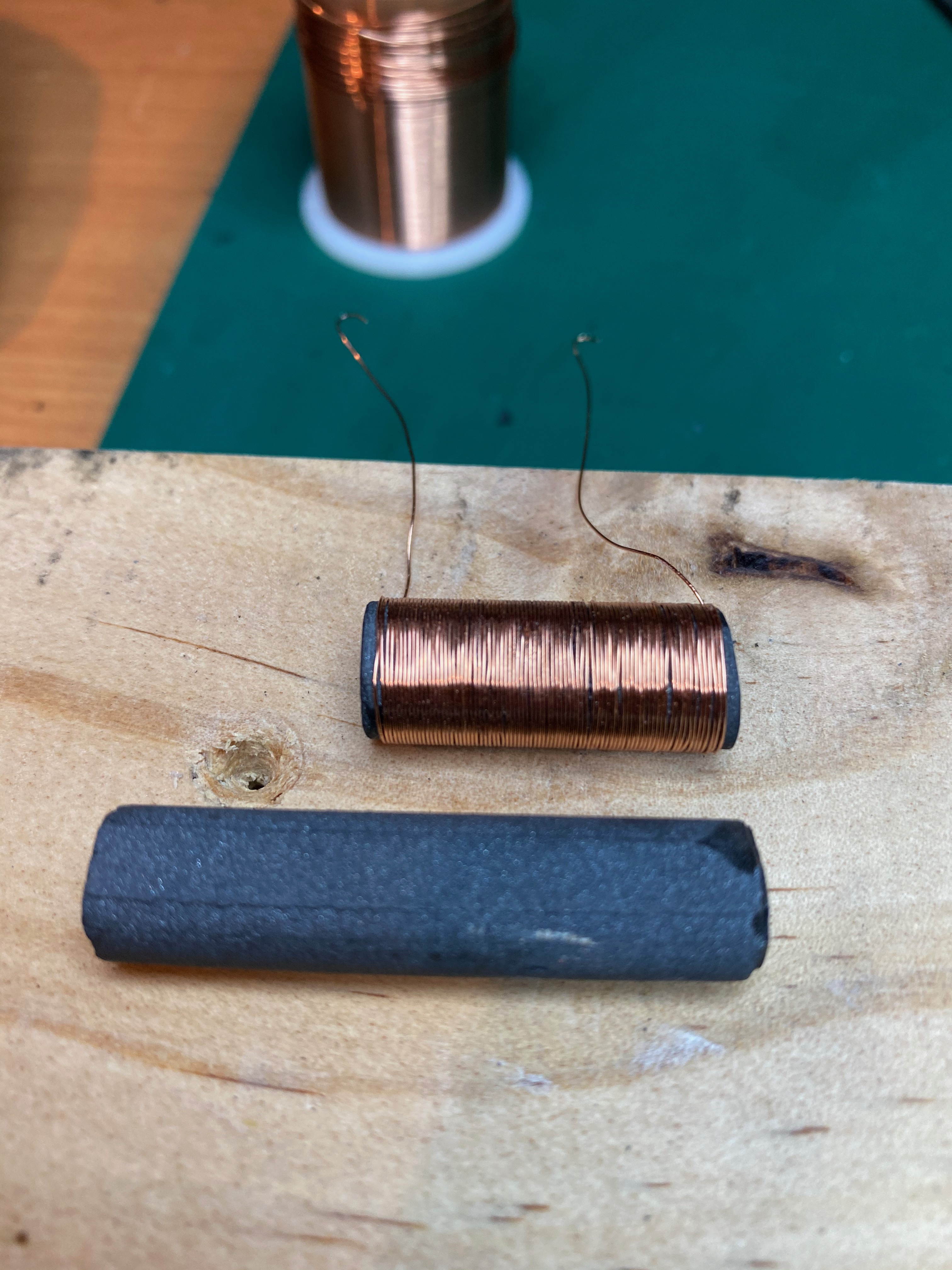
Supplies acquired! @TomHarkness suggested 9mm ferrite rod and 0.25mm enamel wire as a place to start, with the rod cut down to about 2.5cm


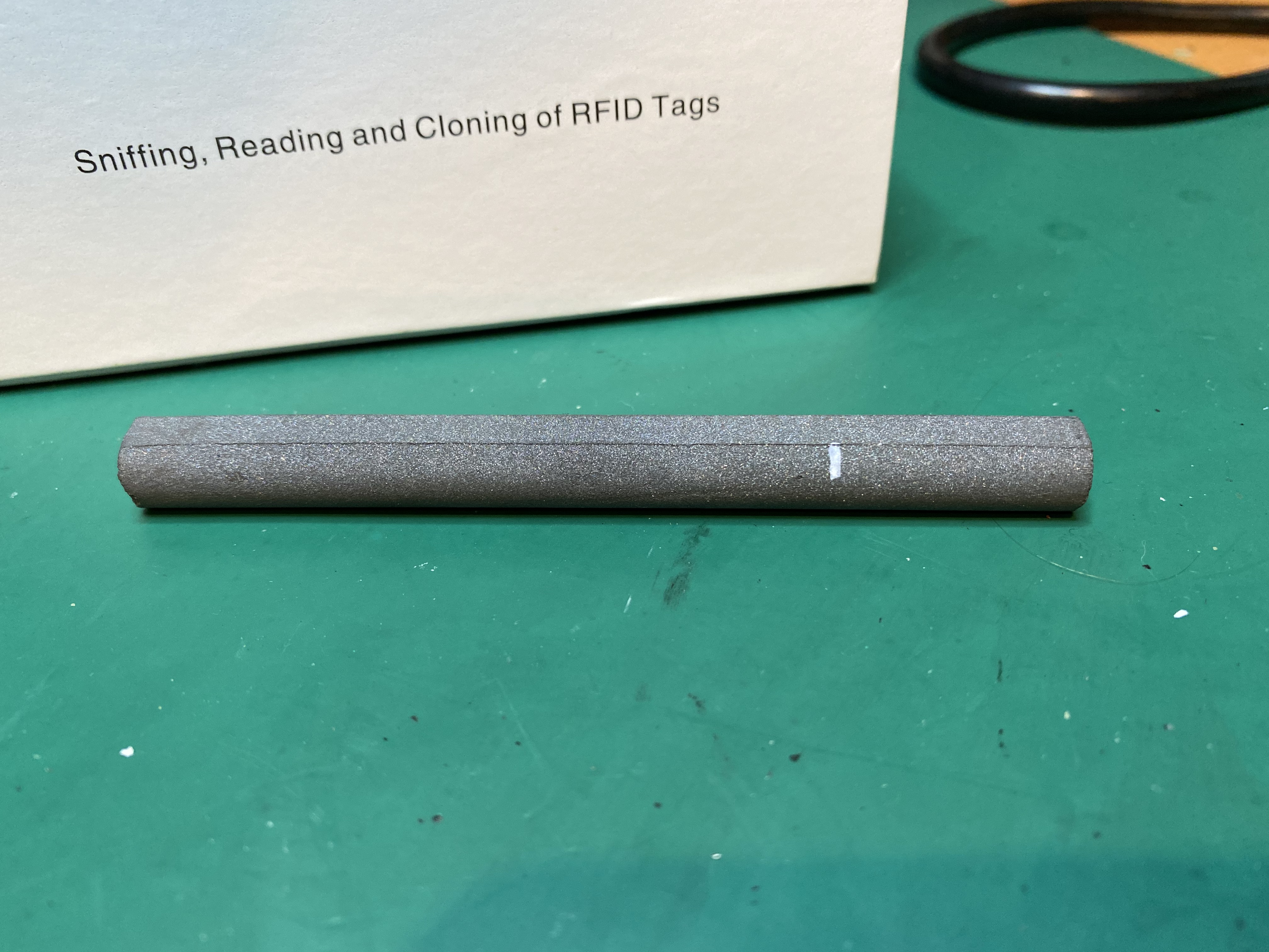
The Dremel probably wasn’t the right tool to use for this, but its what I had. Take it slow, wear eye protection!

I found that winding the coil is all in the fingers, again a tip from Tom, a drop of superglue at the start and the middle as you go will hold it in place and make your life easier.

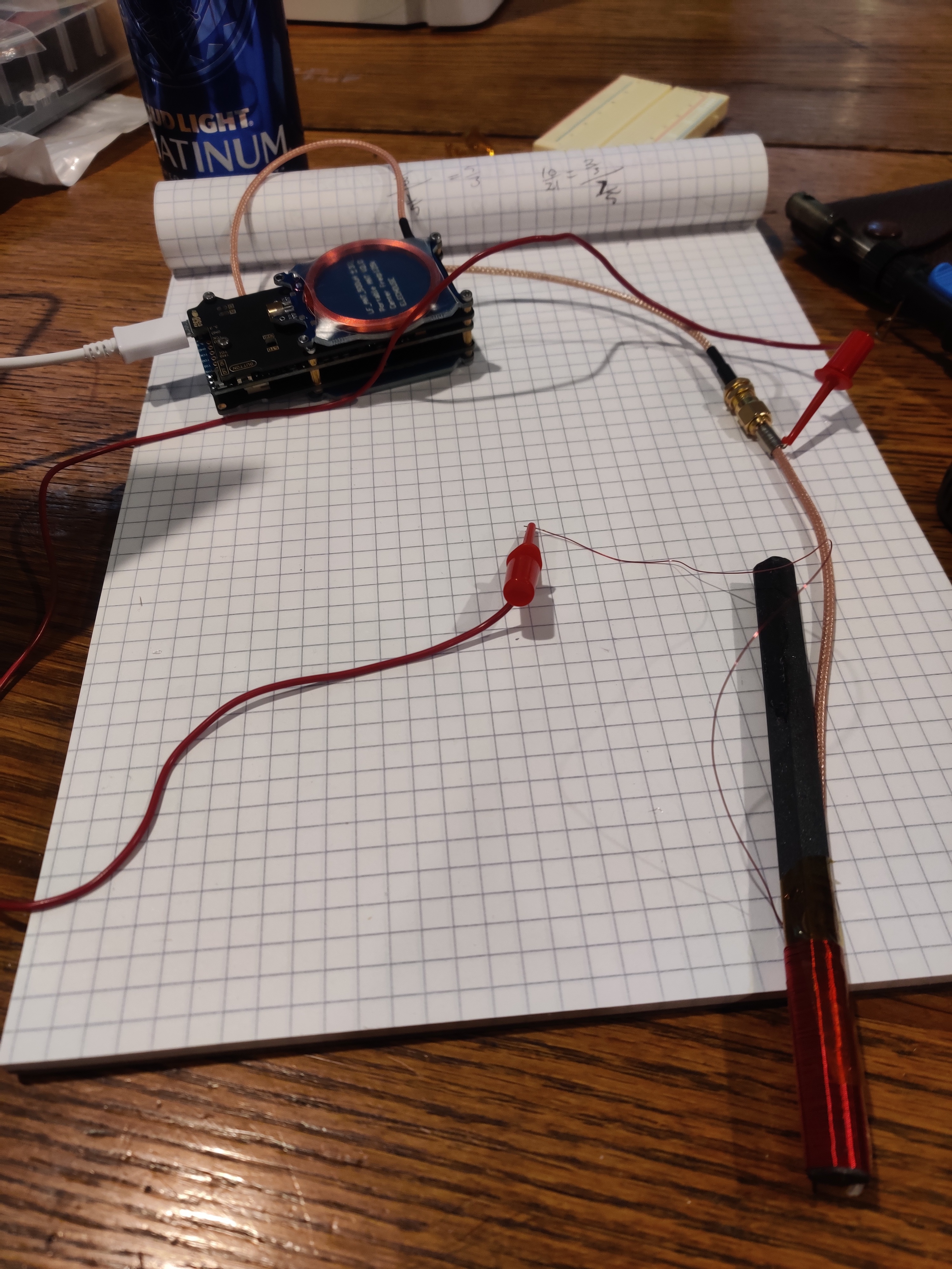
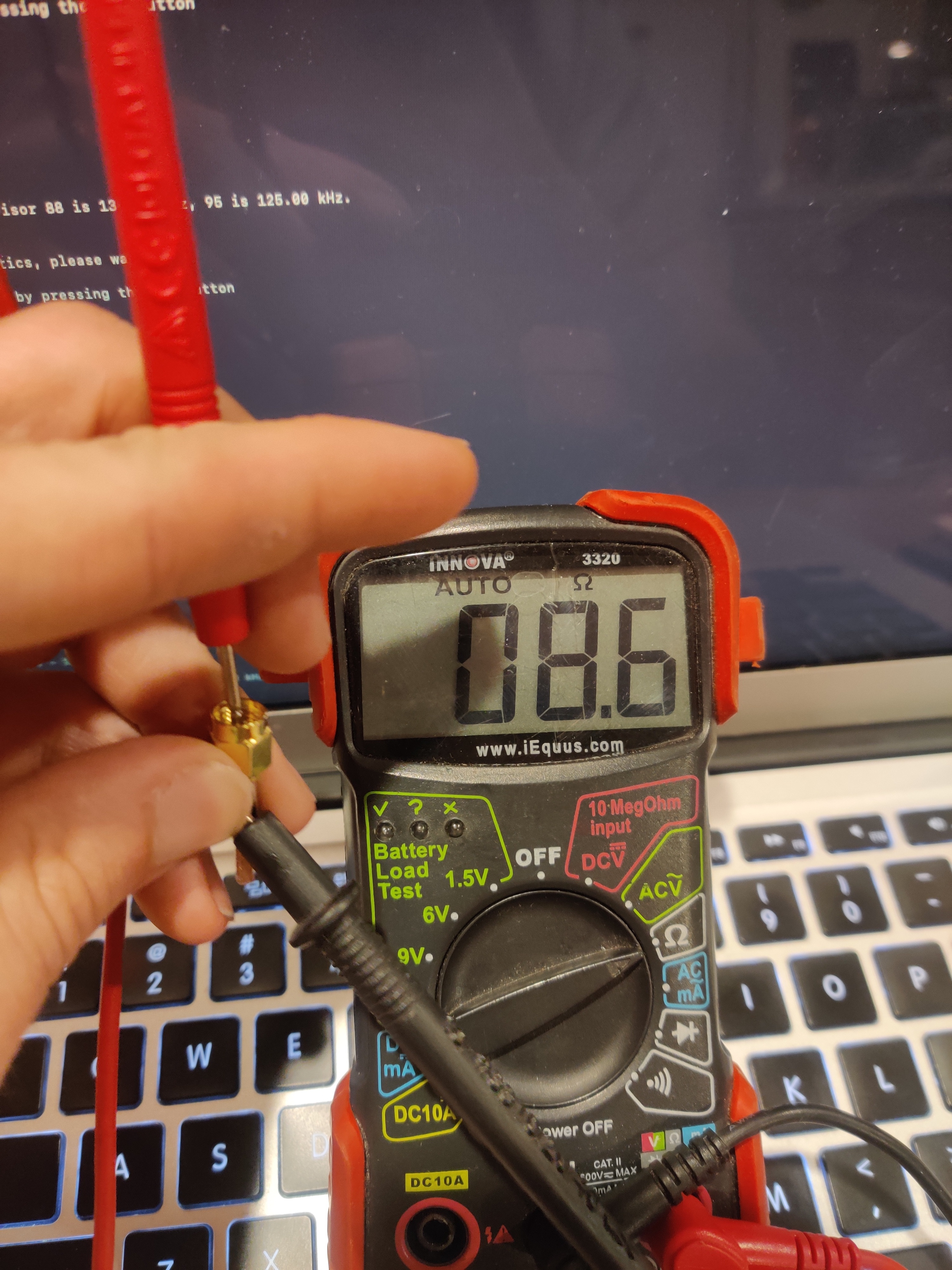
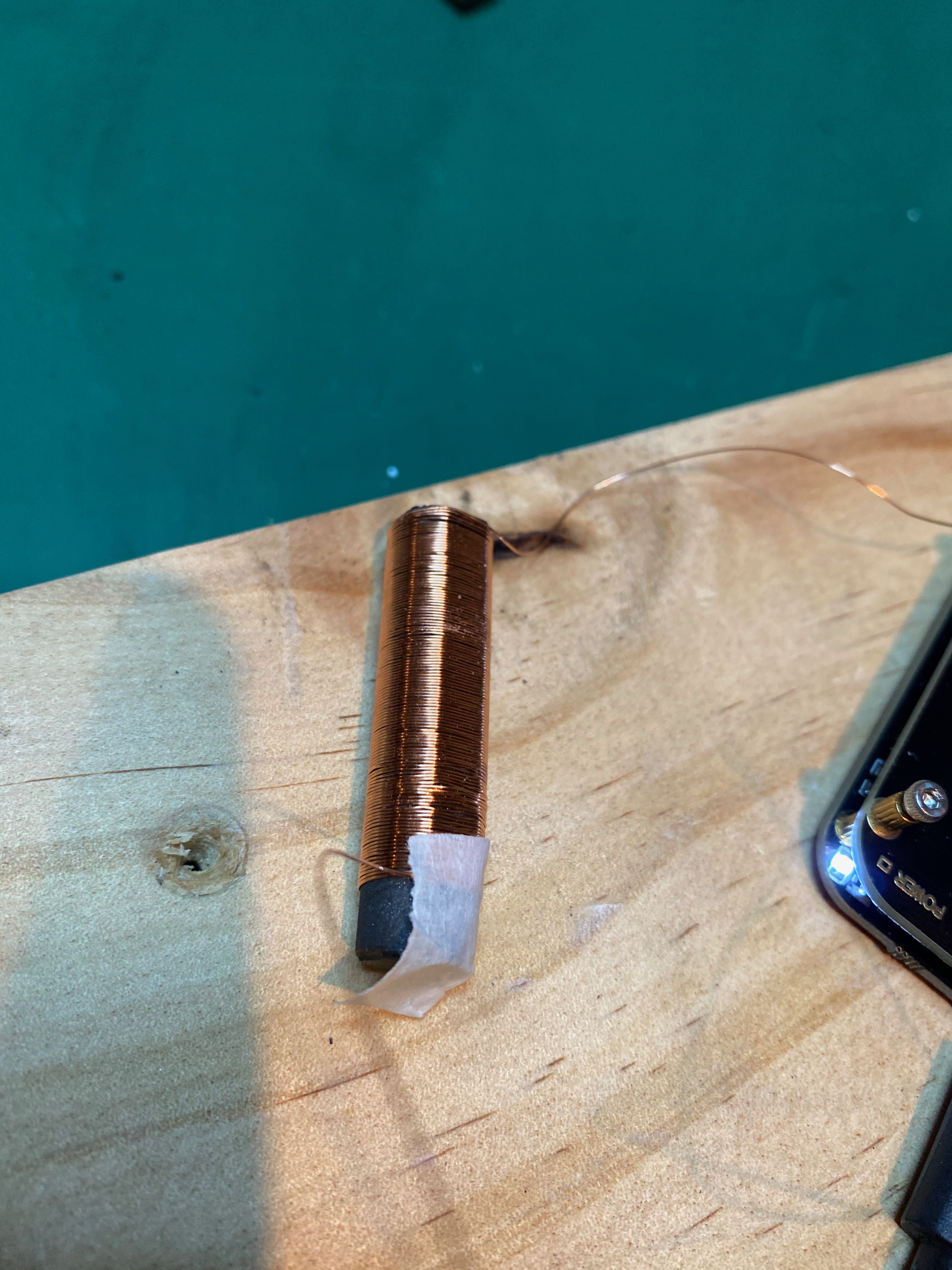
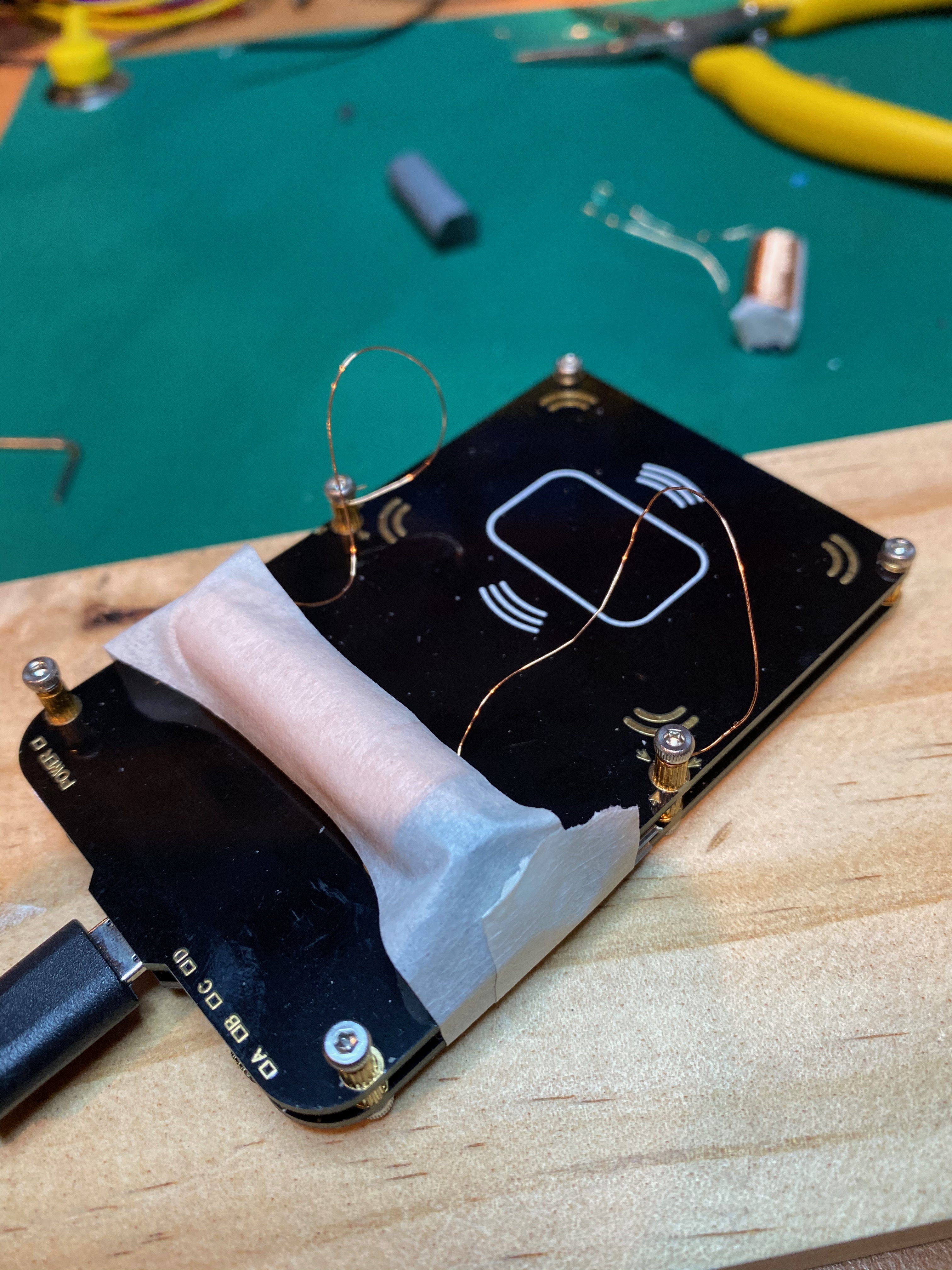
Once I was getting close to the end, I found a bit of masking tape holds the end enough to test tuning, I wanted to avoid glue here until I tested it so I could add or remove turns as needed. At this point, I connected the ends to my proxmark, leaving plenty of extra wire on the end incase i needed to add turns and…

tune1

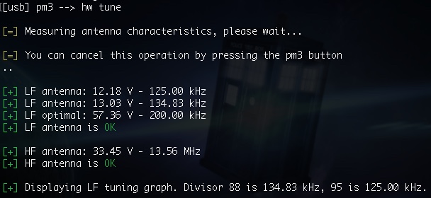
Damn, 222.22kHz - a little bit away from the 125kHz I’m looking for. Time to add more turns and try again…


tune2

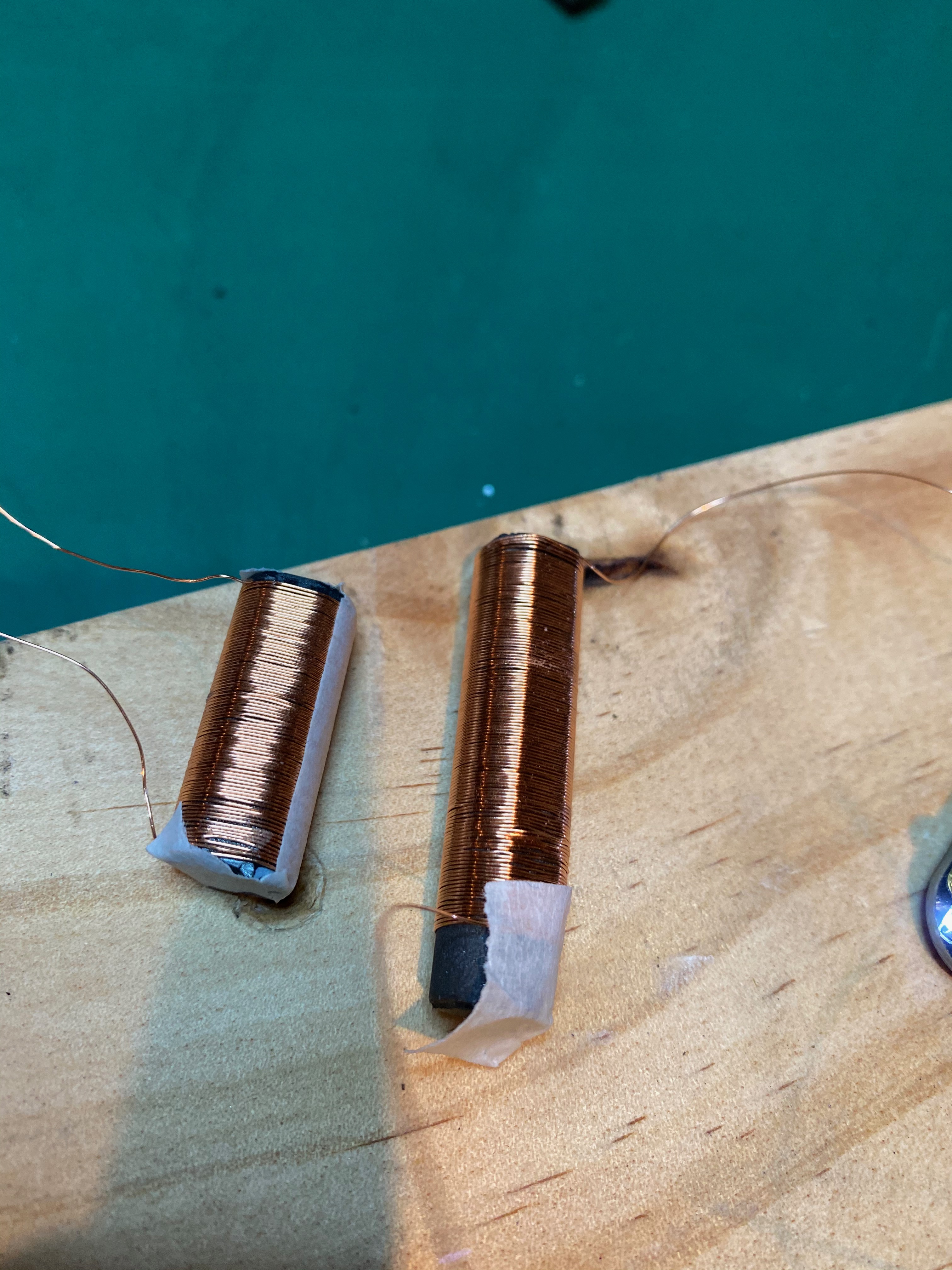
Better, but not better enough. And I’m out of room for more turns… damn… not sure why I was so far off, I imagine the dimensions on my supplies may be slightly off and messing up the number of turns. Well, I need more! Let’s try this again…

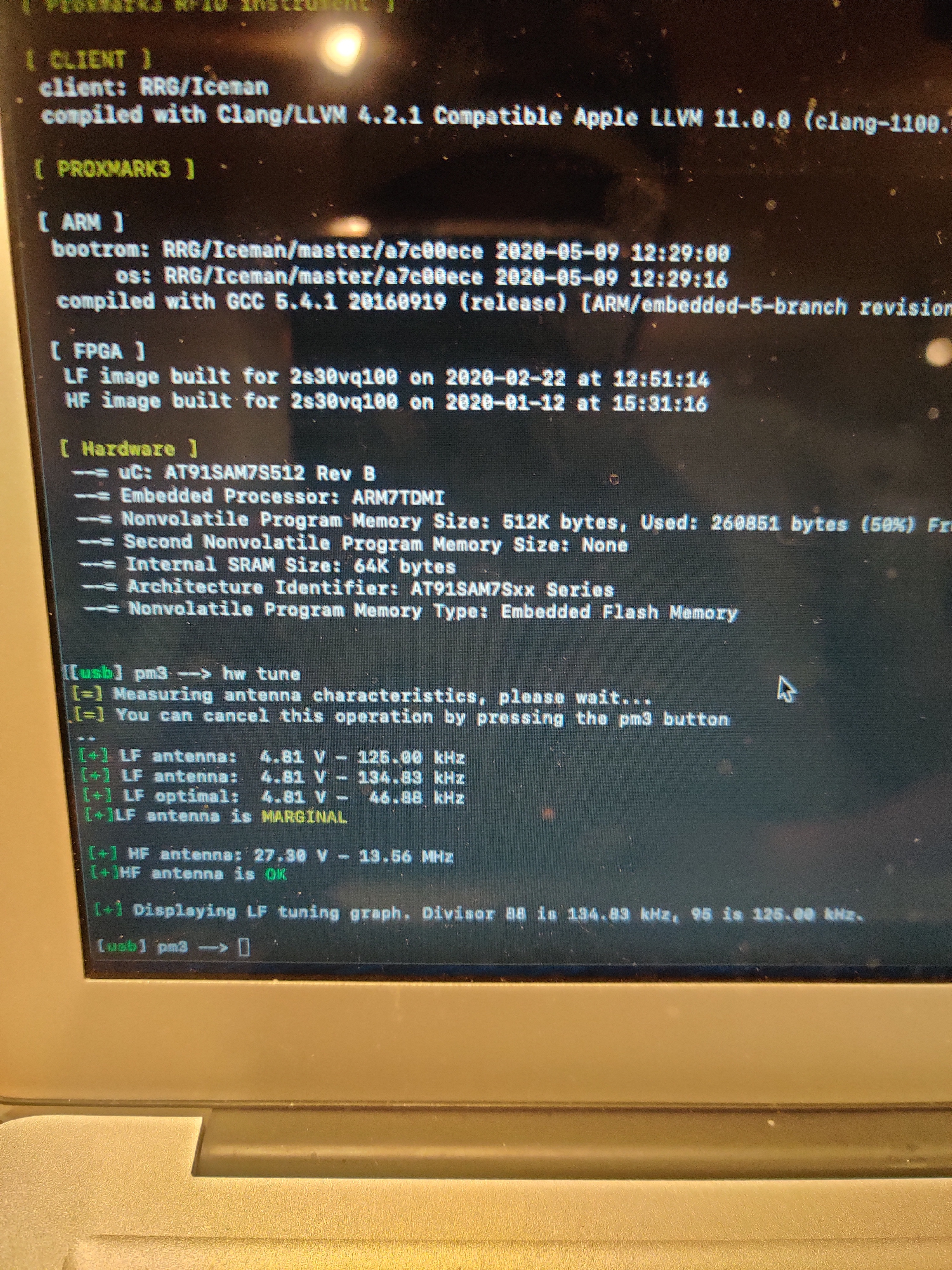
Alright, time for another test…

tune3

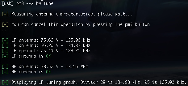
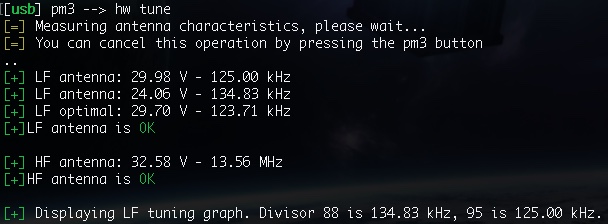
Wow, much better! At this point, no joke, I took off exactly 1 turn and ran it again.

tune4

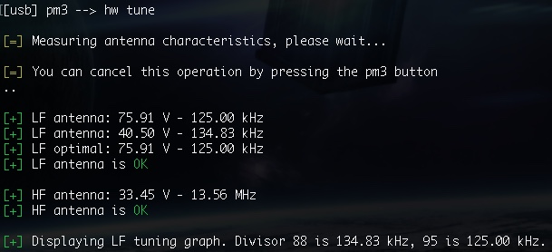
Yeah, I know, I didn’t believe I hit it exactly either!

It’s not as impressive as the ProxLF antenna, but I’m now getting reads a little bit off the antenna to my tag that is implanted pretty deeply.

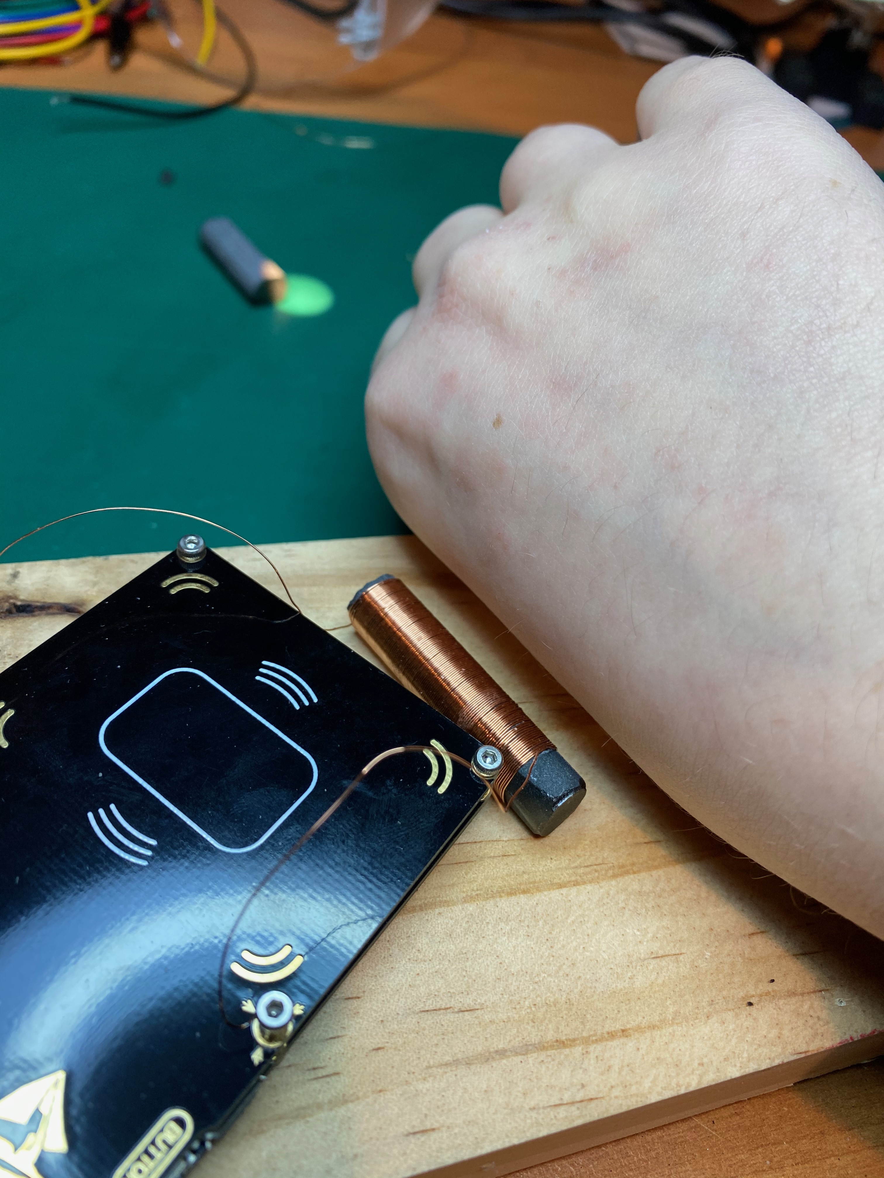
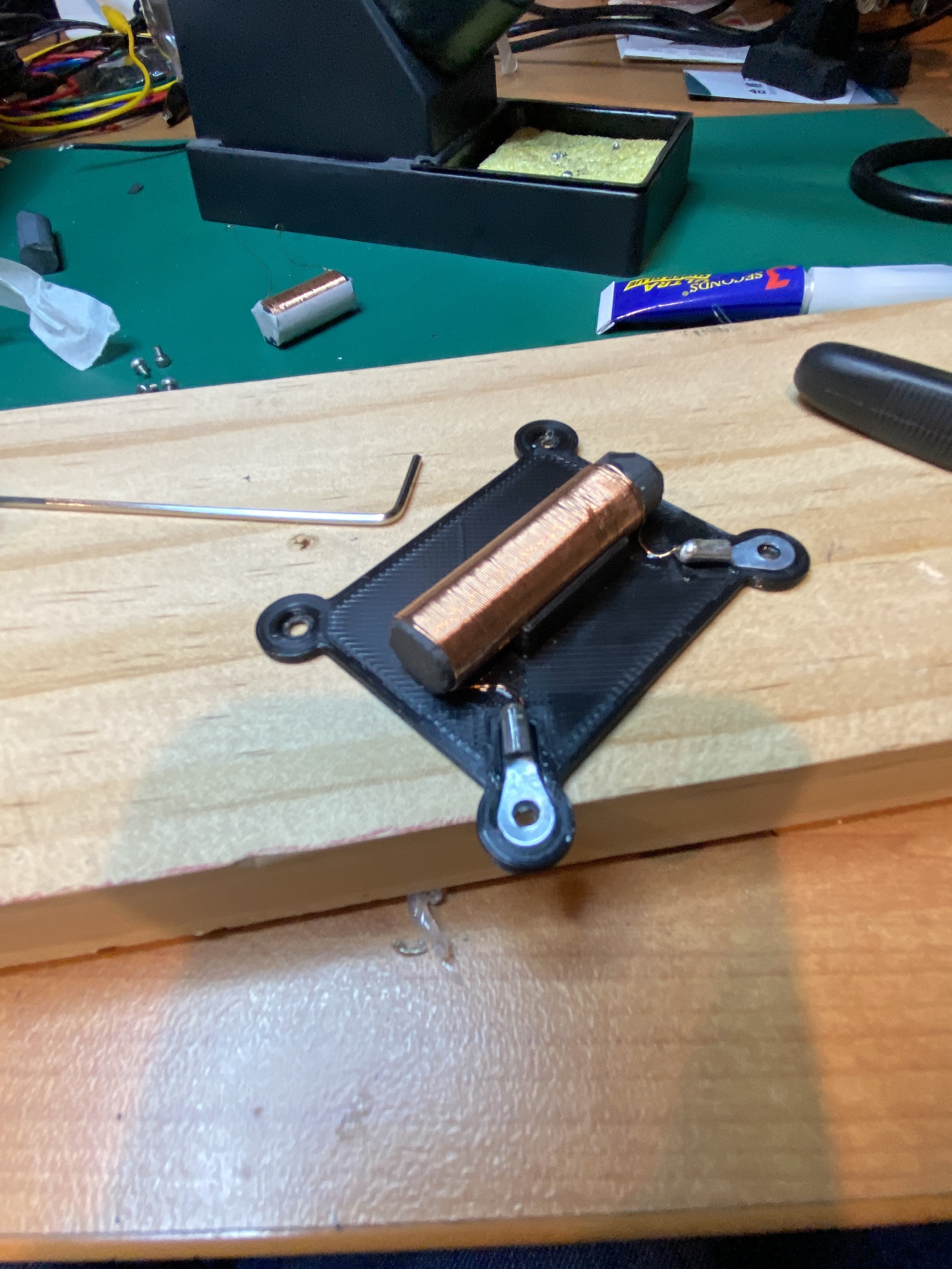
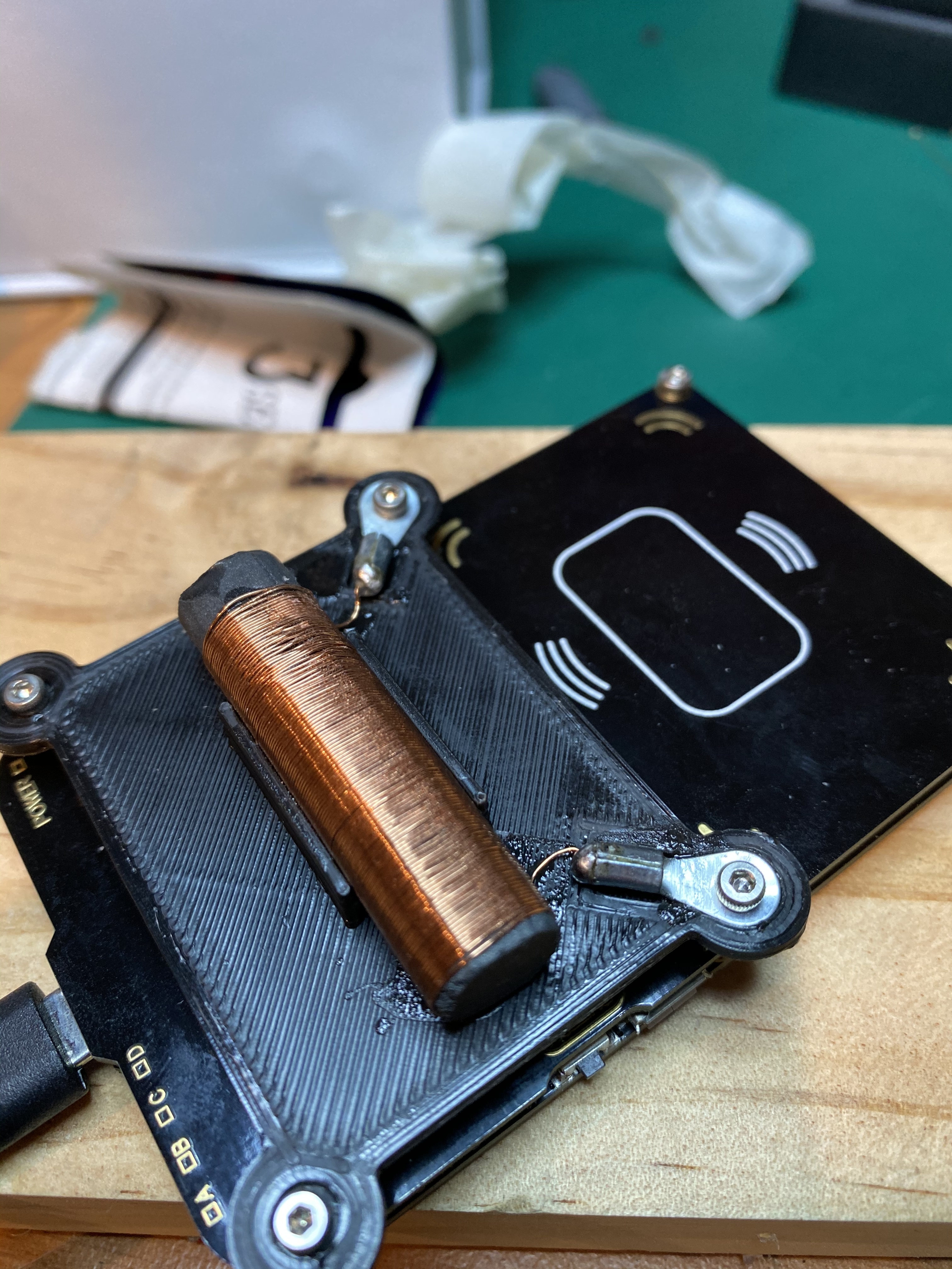
Watch this space! 3D printed holder to screw this in to the Proxmark coming, in the meantime, check out this installation!

Read performance is far better than the stock antenna! But I’m still struggling to get lf t55xx detect or trace commands to work. Not sure what’s going on here as I managed to get them working on even the stock antenna (this antenna does them with a test t5577 card too) - A little more playing to go, but so far I’m very happy with this thing!

Thanks again @TomHarkness - would love to hear your thoughts on how I went and suggestions for next time!

Thats all for this chapter, thanks for coming to my TED Talk!

21 Likes

That’s so damn cool!
Well done Sir!

1 Like

Can this method be used for helping find the right frequency for the bracelets?

Probably not unfortunately, but I’m not certain.

Might be a better question for @TomHarkness or the other people in that thread, but my understanding is that this coil I’ve made and tested with my Proxmark isn’t “tuned”, but the circuit including the antenna, the capacitors on the PCB, and other capacitances in the circuit result in a tuned system. If you were to take this antenna and use it with a different RF front end, you may find a different centre frequency.

It might help you get in the ballpark, but I’m not sure how off it would be once connected to your power supply circuit.

3 Likes

Like in the muscle? Or just thick skin?

It’s not in muscle, just under a bit more skin. It gets less range than my brothers on the same locks by a few mm - Maybe 3-5 on an xAC. I’ve always attributed it to being a bit deeper in the hand, but could be wrong, may just be manufacturing tolerance.

3 Likes

For 1 this is a LF coil and the bracelets are targeting HF chips. I have already tried LF and it is much easier to do. If you look through that thread it has been mentioned it would be easier. Since I am interested in the HF fingernails which work well with my last coil design. I have put my work with the bracelets on the back burner for now, although if I am in the mood to work on it there is plenty of optimization to be done.

1 Like

Nicely done indeed @Compgeek - this is exactly the method that I was trying to explain earlier.

A few notes that might help you - 70v for the easy is way way too high. I’m unsure if it will fry anything on the pm3 BUT the t55 in the xrm does have over voltage protection built in - I hit a wall with this when designing the ProxLF in terms of upping the voltage and chose not to go above 26V for that reason. In terms of making that pm3 perform as best as it can - you want to aim for around what the original antenna voltage is.

3 Likes

Thanks @TomHarkness - any advice for mk2 on how I can bring the voltage down without detuning? Is this something that could be simple to tweak?

Good news is nothing on the board seems to have cooked - back to stock antenna and everything seems fine

In the meantime, this is the result of the 3D printing - I think it came up pretty neat!

8 Likes

Figured it out!

I grabbed out my cheap LCR, wasn’t looking for exact numbers, just wanted to figure out a ballpark.

My inductance was slightly lower for a better tune, and resistance slightly higher, but I didn’t think either would be enough to make a difference… I was wrong… 0.02mH between the two is enough at 125kHz to lower the reactance enough to result in the crazy numbers I was getting. Adding a series resistor was all it needed to tame it back.

I did some bench testing of different values (not soldered, just held in place with clips) and settled on 47R, which brought me down to 26V.

I should have gone lower, because once I soldered it and had a better connection it got back up to just under 30V - for my use that’s good enough though!

tune5

I don’t get the crazy range that 70V afforded me, but I get a very usable range for what I need. I can now just slap it on my hand in roughly the right spot and consistently get reads, automatic chipset detection, t55 detects, and trace info!

There are certainly things I’d do different if i were to do this again, but I think that’s the end of this saga for now.

Thanks for playing along everyone, and again @TomHarkness, thanks! If you find yourself in Victoria once this virus is gone, I owe you a drink!

5 Likes


My turn. Will post results when done.

4 Likes

Sending sciencey waves your way

3 Likes


First attempt, voltage wayyyy low optimal frequency super low too.

2 Likes

Be aware the length of the rod significantly effects the inductance of the coil as a whole I believe.

2 Likes

So after taking off like 50 turns with basically no change I broke the rod down to about 25mm. Still no significant change though. I chose to wrap the rod with capton tape to prevent scratches to the enamel on the wire. I have unwound and rewound it differently (new wire) to no success. Still stuck around 4.8v and exactly at 46.88 khz still. I unfortunately don’t have a LCR, which is something that I need to invest in but haven’t yet. I’m wondering if the issue is that I’m using about a foot of coax cable between the proxmark3 and the antenna. I still feel like I should see some kind of change by adding/removing coils but other than .1v changes I’m seeing nothing change. I am no expert in rf anything but I am interested. My ferrite rod is 10mm with 2 flats 180° off from each other, and my wire is 30 awg) Any ideas/recommendations? (Other than getting an LCR, which is already on my list)

1 Like

Voltage is way too low!

Definitely shorten the wire length. With it saying the same voltage at all 3 frequencies, I’m guessing it’s too low for it to detect tuning?

1 Like

Forgive the photo, phone in one hand, 2 probes and an rp-sma connector in the other. If I use 2 hands it’s a 0 ohm short. I couldn’t let it go before bed that the readouts were so consistently bad and unchanging. So if anyone is curious, a shorted plug on the end of your coax pigtail causes the above issues. I feel kinda stupid for letting a quick continuity test slip through my fingers after making the pig tail, but the good news is I get actual changing numbers now, so tomorrow evening I should manage a completed antenna after much fine tuning and beer.

3 Likes

I had a half typed message to tell you to check connectivity :sweat_smile: but I got called away from the computer and forgot :sweat_smile: I feel bad now, caught me out a few times with the clips on the coil where I’d not got the enamel off enough. Glad you solved it! Enjoy the cold one!

2 Likes


Boom. 125.00 kHz, 25.99 V. Gonna make a slick case tomorrow.

11 Likes

Very nice! I love the idea to have it neatly on the coax like that, probe style!

2 Likes